In the previous Episode 9 we learned “never put heavy processing inside an ISR.” But what do you do when you absolutely must transfer a large amount of data?
The answer is DMA (Direct Memory Access).
DMA is hardware that moves data without involving the CPU. The transfer completes while the CPU is free to do other things.
📖 Previous Article
Episode 9: Interrupt Design Anti-Patterns — "Deliberately Break It" to Learn ISR Design
📍 Series Top Page
✅ What you'll be able to do after this article
- Explain why DMA exists from a bus-architecture perspective
- Read STM32's DMA stream/channel mapping table and configure it
- DMA-ify a UART TX and send data with the CPU free
- Implement a transfer-complete callback and safely start the next transfer
- Explain why a buffer-reuse timing mistake corrupts data
Table of Contents
- What Is DMA?
- Why Do We Need DMA?
- STM32’s DMA Architecture
- DMA-ifying UART TX (Practice)
- Throughput and Latency
- Bus Contention
- Common Pitfalls
- Summary
🔌 What Is DMA?
DMA Is a “Dedicated Data-Transfer Hardware Unit, Separate from the CPU”
DMA (Direct Memory Access) is a hardware module that exists independently from the CPU. It is not a memory feature, nor a CPU feature — it is an independent data-transfer engine connected to the bus.
Let’s first see what happens without DMA.
Data Transfer Without DMA
Consider the operation “send a string stored in RAM over UART.”
【Normal Transfer: The CPU Does Everything】

RAM (string buffer)
  │
  │ LDR instruction (CPU reads 1 byte from RAM)
  ▼
CPU (holds data in a register)
  │
  │ STR instruction (CPU writes 1 byte to UART DR register)
  ▼
UART DR register → physically transmitted
Sending 1 byte requires one “LDR → STR” CPU instruction pair. To send 100 bytes, the CPU repeats this 100 times. During that time the CPU can do nothing else.
With DMA
【DMA Transfer: CPU Just Places the Order】

CPU: "DMA, take 100 bytes from this address and send them to UART DR"
  │
  │ (CPU immediately moves to the next task)
  ▼
DMA controller (runs independently)
  │
  ├─ RAM → DMA → UART DR (byte 1)
  ├─ RAM → DMA → UART DR (byte 2)
  ├─     …… (CPU not involved)
  └─ RAM → DMA → UART DR (byte 100) Done!
           │
           └─ Transfer-complete interrupt notifies CPU
The CPU only “places the order,” and is then free to run.
Do All Microcontrollers Have DMA?
No. The presence or absence of DMA varies significantly by microcontroller.
| Microcontroller | DMA |
|---|---|
| Arduino UNO (AVR ATmega328P) | ❌ None |
| Arduino Mega (AVR ATmega2560) | ❌ None |
| STM32F401RE | ✅ DMA1 + DMA2 (8 streams each) |
| ESP32 | ✅ Yes (select peripherals) |
| Renesas RA / RX | ✅ Yes |
| PIC32 | ✅ Yes |
One reason the Arduino UNO can only do blocking transmissions is that it has no DMA. 32-bit microcontrollers like the STM32 ship with DMA as standard.
What Is a “Peripheral”?
The word “peripheral” that appears in DMA explanations is a collective term for all hardware modules other than the CPU and memory.
| Peripheral | Role |
|---|---|
| UART / USART | Serial communication (talking to a PC) |
| SPI | High-speed communication with sensors, SD cards |
| I2C | Communication with sensors and displays |
| ADC | Converts analog voltage to digital value |
| DAC | Converts digital value to analog voltage |
| TIM | Timers and PWM generation |
All of these are hardware operated by reading and writing to specific registers. DMA automatically shuttles data between a buffer in RAM and these peripheral registers.
What “Without CPU Involvement” Really Means
Let’s look at what it means for the CPU to be “involved,” at the hardware level.
Inside a microcontroller, the CPU, DMA, RAM, and peripherals are all connected by the AHB bus (Advanced High-performance Bus) — a shared highway.
Cortex-M4"] DMA["DMA1"] end BUS(["AHB Bus Matrix"]) SRAM["SRAM"] UART["UART2
Peripheral"] CPU --> BUS DMA --> BUS BUS --> SRAM BUS --> UART
Both the CPU and DMA are bus masters connected to the same bus. Either can access RAM or peripherals.
“Without CPU involvement” means “instead of the CPU occupying the bus to repeat LDR/STR, the DMA uses the bus to move data.” The CPU doesn’t need to use the bus during that time — it can focus on computation and control logic.
DMA is not a “subordinate” of the CPU — it’s an independent hardware module that shares the same bus. Rather than “DMA works while the CPU sleeps,” the more accurate picture is: “the CPU and DMA are doing different jobs in parallel.”
- CPU → control logic, computation, decision-making
- DMA → simple data transport
This division of labor dramatically improves the efficiency of an embedded system.
DMA’s Three Elements
| Element | What it is | Example (UART TX) |
|---|---|---|
| Source | Where to read from | RAM buffer |
| Destination | Where to write to | USART2->DR register |
| Count | How many to transfer | Number of bytes to send |
Each also has an address-increment setting:
| Source | Destination | |
|---|---|---|
| UART TX | ✅ Increment (advance to next byte) | ❌ Fixed (DR register is always the same address) |
| ADC → RAM | ❌ Fixed (DR register) | ✅ Increment (advance to next array element) |
⚡ Why Do We Need DMA?
Interrupts Still Leave the CPU Occupied
In interrupt-based UART transmission (Episodes 8–9), every time UART finishes one byte an interrupt fires, and the CPU writes the next byte to the DR register — over and over.
Byte 1 done → interrupt → CPU writes byte 2 to DR
Byte 2 done → interrupt → CPU writes byte 3 to DR
    …… (repeats for every byte)
Sending 100 bytes triggers 100 interrupts, and the CPU runs an ISR each time.
⚠️ Image not found: without_dma.png
With DMA, Only One Interrupt — at Completion
CPU tells DMA: "send N bytes from this buffer to UART DR"
  ↓
DMA autonomously transfers one byte at a time (CPU can do other work)
  ↓
Transfer complete → DMA fires one interrupt
  ↓
CPU "prepares the next data" — that's all
⚠️ Image not found: with_dma.png
DMA is a mechanism for making the CPU idle. Because the CPU doesn’t have to babysit the transfer, that time is free for “work that truly needs the CPU” — reading sensors, running control algorithms, updating displays.
Interrupt → “Call the CPU on an event-driven basis”
DMA → “Move data without calling the CPU at all”
These two are not opposites — they’re used together.
🏗 STM32’s DMA Architecture
DMA1 and DMA2
The STM32F401RE has DMA1 (8 streams) and DMA2 (8 streams).
- DMA1: Handles APB1 peripherals (USART2, I2C1, SPI2, etc.)
- DMA2: Handles APB2 peripherals (USART1, SPI1, ADC1, etc.) + memory-to-memory transfers
Streams and Channels
Each DMA has 8 streams (Stream0–7); each stream selects one of 8 channels (Channel0–7). The channel determines which peripheral’s DMA request is accepted.
| DMA | Stream | Channel | Peripheral |
|---|---|---|---|
| DMA1 | Stream6 | Channel4 | USART2_TX ← used in this episode |
| DMA1 | Stream5 | Channel4 | USART2_RX |
| DMA1 | Stream0 | Channel1 | I2C1_RX |
| DMA2 | Stream7 | Channel4 | USART1_TX |
The stream/channel mapping differs between microcontrollers. For the STM32F401, verify using the RM0368 (Reference Manual), “Table: DMA1 request mapping” in the DMA chapter. Configuring with CubeMX automatically enters the correct values.
DMA Transfer Modes
| Mode | Description | Use case |
|---|---|---|
| Normal | Transfer a set count, then stop | UART TX (one-shot) |
| Circular | Reuse buffer continuously | ADC sampling, audio |
| Memory-to-Memory | RAM-to-RAM copy | memcpy replacement (DMA2 only — DMA1 does not support this) |
🛠 DMA-ifying UART TX (Practice)
CubeMX Configuration
- USART2 → Mode: Asynchronous (Baud: 115200)
- DMA Settings tab → Add →
USART2_TX- Direction: Memory To Peripheral
- Mode: Normal
- Increment: Memory ✅ / Peripheral ❌
- NVIC Settings → DMA1 stream6 global interrupt → Enable ✅
⚠️ Image not found: cubemx_dma.png
Generated Code
Key parts of the initialization code CubeMX generates:
/* Excerpt from MX_DMA_Init() in main.c */
hdma_usart2_tx.Instance                 = DMA1_Stream6;
hdma_usart2_tx.Init.Channel             = DMA_CHANNEL_4;
hdma_usart2_tx.Init.Direction           = DMA_MEMORY_TO_PERIPH;
hdma_usart2_tx.Init.PeriphInc           = DMA_PINC_DISABLE;   /* DR fixed */
hdma_usart2_tx.Init.MemInc              = DMA_MINC_ENABLE;    /* advance through buffer */
hdma_usart2_tx.Init.PeriphDataAlignment = DMA_PDATAALIGN_BYTE;
hdma_usart2_tx.Init.MemDataAlignment    = DMA_MDATAALIGN_BYTE;
hdma_usart2_tx.Init.Mode                = DMA_NORMAL;
hdma_usart2_tx.Init.Priority            = DMA_PRIORITY_LOW;
Implementation: DMA Transmission
/* Global buffer (must remain in RAM throughout the DMA transfer) */
static uint8_t g_tx_buf[64];
volatile bool g_tx_busy = false;   /* <stdbool.h> */

/* Start a DMA transmission */
void uart_send_dma(const char *str)
{
    uint16_t len = strlen(str);
    if (len > sizeof(g_tx_buf)) len = sizeof(g_tx_buf);

    /* Wait if a transfer is already in progress (or handle as error) */
    while (g_tx_busy);   /* ← polling — see note below */

    memcpy(g_tx_buf, str, len);
    g_tx_busy = true;

    HAL_UART_Transmit_DMA(&huart2, g_tx_buf, len);
    /* ← CPU returns here immediately; DMA handles the rest */
}

/* Transfer-complete callback (called from the DMA interrupt) */
void HAL_UART_TxCpltCallback(UART_HandleTypeDef *huart)
{
    if (huart->Instance == USART2)
    {
        g_tx_busy = false;   /* allow the next transmission */
    }
}
/* while(1) in main */
while (1)
{
    char msg[32];
    snprintf(msg, sizeof(msg), "tick=%lu\r\n", g_tim2_tick);

    uart_send_dma(msg);   /* CPU returns immediately */

    /* CPU is free to do other work */
    HAL_GPIO_TogglePin(GPIOA, GPIO_PIN_5);
    HAL_Delay(500);
}
while (g_tx_busy) stalls the CPU until the previous transfer finishes — polling. When transmission frequency is high, this defeats the non-blocking benefit of DMA. In production code, consider returning an error or skipping the send when busy to preserve non-blocking behaviour.
/* Non-blocking design */
if (g_tx_busy) return HAL_BUSY;   /* let the caller decide */
HAL_UART_Transmit() is blocking (waits until transmission completes); HAL_UART_Transmit_DMA() is non-blocking. Control returns to the caller the instant the function is called, while DMA continues the transfer in the background.
This is why it is critical not to reuse the buffer before the transfer completes (details in the pitfalls section).
Verification: Measuring with DWT CYCCNT
/* Measure CPU time from DMA launch to callback */
uint32_t t_start = DWT->CYCCNT;
HAL_UART_Transmit_DMA(&huart2, g_tx_buf, len);
uint32_t t_launch = DWT->CYCCNT - t_start;
/* t_launch ≈ a few tens to a few hundred cycles (just the "launch" cost) */

/* For comparison: blocking version */
t_start = DWT->CYCCNT;
HAL_UART_Transmit(&huart2, g_tx_buf, len, HAL_MAX_DELAY);
uint32_t t_blocking = DWT->CYCCNT - t_start;
/* t_blocking ≈ bytes × 86.8µs × 84 cycles/µs (CPU occupied the whole time) */
Comparison example for a 64-byte transmission:
| Method | CPU time occupied |
|---|---|
HAL_UART_Transmit() (blocking) |
≈ 47,000 cycles (≈ 560 µs) |
HAL_UART_Transmit_DMA() (DMA) |
≈ 200 cycles (≈ 2.4 µs) |
The blocking CPU occupancy scales linearly with the byte count:
t_{\text{blocking}} \approx N_{\text{bytes}} \times \frac{10\,\text{bits}}{f_{\text{baud}}} \times f_{\text{CPU}}With DMA, this cost collapses to a fixed \approx 200\,\text{cycles} launch overhead — independent of N_{\text{bytes}} .
📊 Throughput and Latency
Let’s clarify why DMA feels “faster.”
Throughput (Transfer Volume per Unit Time)
Whether or not you use DMA, the physical transfer speed of UART does not change. 115200 bps is 115200 bps.
What DMA improves is not throughput — it’s the time the CPU has available for other work.
Latency (Responsiveness)
With DMA, the “waiting time” for a UART transmission is nearly zero from the CPU’s perspective.
【Blocking】
CPU locked to transmission ─────────────────────────── freed
               ↑TX start                             ↑TX complete

【DMA】
CPU issues start ─ freed
              ↑                DMA transfer complete
                               ↑callback via interrupt
This difference is the “latency improvement.” The CPU can move on to the next task immediately.
🔀 Bus Contention
AHB Bus Matrix
The STM32F4 uses an AHB (Advanced High-performance Bus) Matrix structure. The CPU and DMA exist as independent bus masters and share the same bus.
Cortex-M4"] DMA["DMA1"] BUS(["AHB Bus Matrix"]) SRAM["SRAM"] Flash["Flash"] APB["APB1/APB2
Peripherals"] CPU --> BUS DMA --> BUS BUS --> SRAM BUS --> Flash BUS --> APB
When Contention Occurs
If the CPU and DMA try to access the same memory simultaneously, one of them must wait.
CPU: about to read g_tx_buf (in SRAM)
DMA: currently reading data from g_tx_buf (in SRAM)
  → Bus arbitration fires → one party waits 1 cycle
Bus arbitration is the hardware mechanism that referees competing simultaneous access attempts — the traffic controller of the bus. This situation is called bus contention.
The STM32F4 AHB Bus Matrix is not a single shared road — it is a multi-lane interchange. When the CPU is fetching instructions from Flash and DMA is simultaneously accessing SRAM, they travel on separate bus paths and do not conflict.
Contention only occurs when both the CPU and DMA access SRAM at the same time. If, say, DMA is reading the UART TX buffer from SRAM while the CPU also tries to read or write SRAM, bus arbitration fires. For most UART workloads the overlap is rare and brief.
Bus contention is unavoidable, but its impact is typically small (a few to a few dozen cycle stalls). For slow, periodic transfers like UART DMA, it’s almost never a problem.
Contention becomes significant when DMA is running high-bandwidth, continuous transfers (high-speed ADC, audio, cameras). In those cases, separating transfer buffers across internal SRAM and CCM (Core-Coupled Memory) may be needed.
⚠️ Common Pitfalls
Pitfall 1: Overwriting the Buffer Before the Transfer Completes
/* ❌ Overwriting the buffer while DMA is still reading it */
uint8_t tx_buf[64];

HAL_UART_Transmit_DMA(&huart2, tx_buf, 32);
/* While DMA is still reading tx_buf… */
memset(tx_buf, 0, 64);   /* ← Corrupts the buffer! */
DMA is still reading the old buffer, but the CPU overwrites it. The transmitted data is corrupted.
/* ✅ Confirm completion via callback before the next operation */
volatile uint8_t g_tx_done = 1;

void HAL_UART_TxCpltCallback(UART_HandleTypeDef *huart)
{
    g_tx_done = 1;
}

/* Check the done flag before transmitting */
while (!g_tx_done);   /* wait for the previous transfer to finish */
g_tx_done = 0;
memcpy(tx_buf, new_data, len);
HAL_UART_Transmit_DMA(&huart2, tx_buf, len);
Pitfall 2: Using a Local (Stack) Variable as a DMA Buffer
/* ❌ Using a stack-local variable as a DMA buffer */
void send_message(void)
{
    char buf[32] = "Hello DMA!\r\n";
    HAL_UART_Transmit_DMA(&huart2, (uint8_t*)buf, 12);
    /* ← When the function returns, the stack is freed.
          DMA is still reading that "former stack" area! */
}
DMA buffers must be global variables or static local variables.
/* ✅ static keeps it alive beyond the function scope */
void send_message(void)
{
    static char buf[32];
    snprintf(buf, sizeof(buf), "Hello DMA!\r\n");
    HAL_UART_Transmit_DMA(&huart2, (uint8_t*)buf, 12);
}
Pitfall 3: Misusing volatile on DMA Buffers
You might want to mark a DMA-written buffer (e.g. a receive buffer) as volatile, but when using HAL you need to be careful.
/* Tricky example: volatile uint8_t as a DMA buffer */
volatile uint8_t rx_buf[64];

/* Passing a volatile pointer to HAL_UART_Receive_DMA() may
   produce a compiler warning (HAL doesn't expect volatile) */
Because the HAL DMA driver manages cache internally, the safer approach on the application side is to omit volatile and instead control access timing via callbacks.
Pitfall 4: D-Cache and Coherency Problems
This problem applies to any MCU that has a D-Cache (data cache) — not just the STM32F7/H7. MCUs based on Cortex-M7 or higher, such as NXP i.MX RT, Renesas RZ, and the high-performance lines from various vendors, are all equally affected.
Because DMA accesses RAM directly without going through the cache, the CPU’s cached view of memory and the actual RAM contents can go out of sync (coherency problem). The STM32F401 has no D-Cache, so this never occurs in this series — but any MCU with D-Cache requires explicit handling when using DMA.
RX Direction (DMA → RAM → CPU) Failure
DMA writes received data to rx_buf in RAM (bypasses cache)
   ↓
CPU tries to read rx_buf
   → Cache still holds stale data (zeros or data from previous transfer)
   → CPU reads from cache, not RAM ← corrupted
Symptom: Buffer reads as all zeros, or unchanged from the previous transfer. Inserting a printf “fixes” it (the memory access flushes the cache, making it non-reproducible).
TX Direction (CPU → RAM → DMA) Failure
CPU writes new data to tx_buf
   → Write-back cache: data is in cache but not yet written to RAM
   ↓
DMA reads tx_buf directly from RAM → sends stale data ← corrupted
Symptom: Transmitted data is the same as the previous transfer, or is garbage.
Fix: SCB_CleanDCache / SCB_InvalidateDCache
/* ---- After RX: invalidate cache so CPU reads fresh data from RAM ---- */
void HAL_UART_RxCpltCallback(UART_HandleTypeDef *huart)
{
    SCB_InvalidateDCache_by_Addr((uint32_t*)rx_buf, sizeof(rx_buf));
    process_received_data(rx_buf);   /* data is now up to date */
}

/* ---- Before TX: flush cache to RAM so DMA reads the latest data ---- */
void uart_send_dma(uint8_t *data, uint16_t len)
{
    memcpy(tx_buf, data, len);
    SCB_CleanDCache_by_Addr((uint32_t*)tx_buf, sizeof(tx_buf));
    HAL_UART_Transmit_DMA(&huart2, tx_buf, len);   /* DMA now reads fresh data */
}
The Cortex-M7 L1 data cache has a cache line size of 32 bytes. All cache operations are performed in this 32-byte unit — which is exactly why SCB_InvalidateDCache_by_Addr / SCB_CleanDCache_by_Addr only work on 32-byte-aligned addresses and 32-byte-multiple lengths.
If the buffer address is not 32-byte-aligned, the cache of adjacent variables gets invalidated too, causing corruption in a completely unrelated location.
/* DMA buffers must be 32-byte aligned */
__attribute__((aligned(32))) uint8_t rx_buf[64];
__attribute__((aligned(32))) uint8_t tx_buf[64];
| Function | Behavior | When to call |
|---|---|---|
SCB_CleanDCache_by_Addr() |
Flush cache → RAM (write-back) | Before DMA TX (CPU writes → DMA reads) |
SCB_InvalidateDCache_by_Addr() |
Invalidate cache, force re-read from RAM | After DMA RX (DMA writes → CPU reads) |
| Define non-cached MPU region | Place DMA buffers outside the cached address space | Root-cause fix when many buffers are involved |
Summary
What we learned in this episode:
| Concept | Detail |
|---|---|
| Role of DMA | Transfers data between RAM and peripherals without CPU involvement |
| DMA1 Stream6 Ch4 | Handles USART2_TX on the NUCLEO-F401RE |
| HAL_UART_Transmit_DMA() | Non-blocking. CPU regains control immediately |
| TxCpltCallback | Called after transfer completes. Permit the next transmission here |
| Bus contention | Occurs when CPU and DMA access the same memory simultaneously. Minor impact for slow transfers |
| Buffer management | Never overwrite a buffer mid-transfer. Place buffers in global or static storage |
| D-Cache coherency | On any MCU with D-Cache: call SCB_CleanDCache before TX and SCB_InvalidateDCache after RX. 32-byte alignment mandatory |
Once you master DMA, you can assign priority to the CPU’s work.
- Work only the CPU can do: control logic, decision-making, state transitions
- Work you can hand off to DMA: simple data transport
The moment you shift from “the CPU carries bytes one at a time” to “DMA handles everything, the CPU does its real job only” — your embedded system design moves up a level.
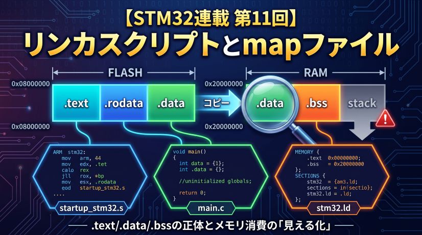
Next up is “Linker Scripts and Map Files (Looking Under the Hood).” We’ll learn where .text, .data, and .bss are placed, and how to track RAM consumption with a map file.
Next Episode
🚀 Episode 11: Linker Scripts and Map Files — Looking Under the Hood
Where are .text, .data, and .bss placed? How to read a linker script, track RAM/Flash usage from a map file, and understand stack and heap placement.
FAQ
Q. Does using DMA make UART transmission “faster”?
The physical transfer speed (bps) does not change. What improves is the time the CPU has available for other processing. The time previously locked up in transmission approaches zero, so the system’s overall responsiveness improves.
Q. Can I call HAL_UART_Transmit_DMA() back-to-back?
Calling it before the previous transfer completes returns an error (HAL_BUSY). The correct pattern is to set a flag in HAL_UART_TxCpltCallback() and check for completion before each new transmission.
Q. When do you use Circular mode?
When you need to stream data continuously — ADC sampling, audio output, and similar cases. In Circular mode, when the transfer completes, DMA automatically wraps back to the start, and the HalfCpltCallback (half complete) and CpltCallback (full complete) enable double-buffered processing.
Q. Can DMA be used with peripherals other than UART?
Yes. Almost all peripherals support DMA — SPI, I2C, ADC, DAC, timers, and more. In particular, running SPI (high speed) and ADC (high-frequency sampling) without DMA is impractical in most real applications.
Once you’ve mastered DMA-ified UART transmission, DMA reception is waiting. HAL_UART_Receive_DMA() enables continuous, CPU-free reception.
Go further with Circular mode — it automatically wraps the DMA back to the start of the buffer, enabling high-speed ADC sampling, audio processing, and any scenario where data flows non-stop. DMA is far more than just UART transmission.