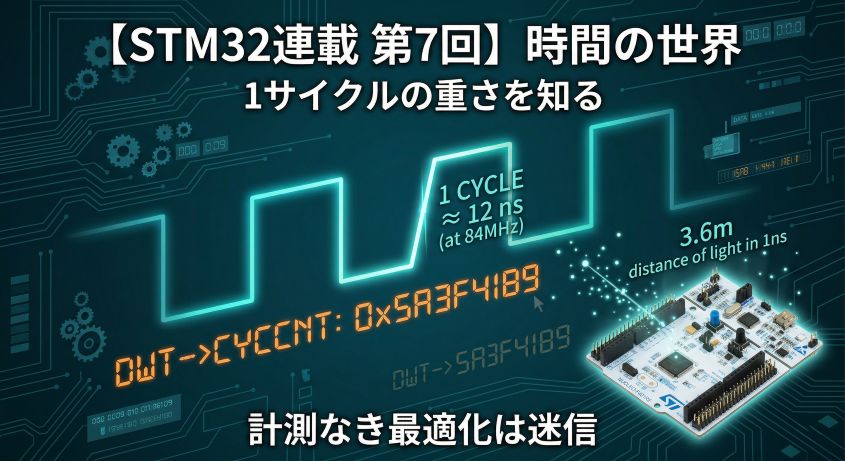
In Episode 7 we acquired the tool to measure execution time using DWT CYCCNT. We could measure — but the CPU was still passive.
“I want to read a sensor every 1ms” — doing this with polling requires a loop that constantly watches HAL_GetTick(). While that loop runs, the CPU can do nothing else.
Interrupts transform the CPU from passive to proactive.
“Force the CPU to respond when something happens” — understanding this mechanism is the true starting point for an embedded engineer who wants to master time.
In this episode we’ll understand “what an interrupt really is” at the mechanism level, then implement a 1ms periodic event generator using TIM2 timer interrupts.
📖 Previous Article
#7: The World of Time — Knowing the Weight of a Single Cycle
📍 Series Index
✅ What You'll Be Able to Do After This Article
- Explain the difference between polling and interrupts, and when to use each
- Describe the vector table structure and the CPU's sequence of actions when an interrupt fires
- Understand the NVIC (priority, enable, clear) and how to configure it
- Draw a diagram showing what gets pushed to the stack during context saving
- Generate a 1ms periodic event with TIM2 interrupts and toggle an LED
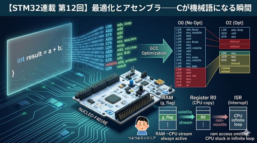
- Explain why
volatileis required for variables shared with an ISR
Table of Contents
- The Limits of Polling (STM32 perspective)
- What Is an Interrupt — The Big Picture
- How the Vector Table Works
- NVIC — The Priority and Permission Manager
- Context Saving — What the CPU Does Automatically
- Implementing TIM2 Interrupts
- Shared Variables in ISRs (volatile and a Teaser for Next Time)
- Summary
⏳ The Limits of Polling (STM32 perspective)
The Cost of “Waiting”
HAL_Delay(1) — which we measured in Episode 7 — is a function that “waits at least 1ms.” What is the CPU actually doing during that wait?
/* HAL_Delay internal implementation (simplified) */
void HAL_Delay(uint32_t Delay)
{
    uint32_t tickstart = HAL_GetTick();
    while ((HAL_GetTick() - tickstart) < Delay)
    {
        /* ← CPU spins here doing absolutely nothing */
    }
}
The CPU does nothing but check a counter, spending roughly 84,000 cycles on standby.
This is polling — continuously checking state at regular intervals. It’s simple, but has real drawbacks:
| Problem | Details |
|---|---|
| CPU monopolization | No other processing can occur while waiting |
| Poor precision | Tied to SysTick period (1ms), making µs-level timing impossible |
| Breaks as tasks grow | Add “1ms sensor read” + “10ms LED update” + “100ms comms” and one loop iteration grows longer — eventually one period starts slipping |
Writing “read sensor every 1ms” with polling
/* ❌ Periodic processing via polling — CPU hammers GetTick() full-time */
uint32_t last_tick = 0;

while (1)
{
    if (HAL_GetTick() - last_tick >= 1)   /* Has 1ms elapsed? */
    {
        last_tick = HAL_GetTick();
        read_sensor();   /* Read sensor */
    }

    /* ↑ The CPU calls GetTick() on every iteration */
    /* Even if there's other work, it must pass through here */
}
Every time you add another task (comms, display, computation), the loop takes longer to complete. The 1ms precision degrades gradually.
Interrupts solve this at the root.
⚡ What Is an Interrupt — The Big Picture
“Answer the phone without forgetting where you were”
In one sentence: an interrupt is “a mechanism by which hardware forces the CPU to ‘handle this right now.’”
Normal execution:
  CPU: running main()...
           ↓
  Timer completes 1ms count!
           ↓
  CPU: suspend main(), save state to stack
           ↓
  CPU: execute TIM2_IRQHandler()
           ↓
  CPU: done, restore state from stack
           ↓
  CPU: resume main() from where it stopped
The analogy: “You’re working, the phone rings, you jot down where you were, answer it, then pick up right where you left off.”

The interrupt analogy: note your work, answer the call, resume exactly where you stopped
Polling vs Interrupts
| Method | Mechanism | Pros | Cons |
|---|---|---|---|
| Polling | CPU checks state periodically | Simple | Wastes CPU, poor precision |
| Interrupt | Hardware notifies CPU | Efficient, high precision | Complex design, bugs lurk |
Use interrupts when you need regular checks with short intervals (<1ms), or when you want to run in parallel with other tasks.
Polling is fine when timing doesn’t need to be exact, or when simplicity matters. Interrupts are powerful, but “avoid them if you can get away without them” is a valid design philosophy.
Interrupt Sources on STM32
The STM32F401RE has two major categories of interrupt sources:
| Category | Examples | Purpose |
|---|---|---|
| Hardware Interrupts (IRQ) | TIM, UART, SPI, GPIO (EXTI), DMA | Notifications from peripherals |
| Exceptions | SysTick, HardFault, SVC, PendSV | System management, error handling |
SysTick is itself a kind of interrupt — the HAL library uses it to update its tick counter every 1ms. In this episode we’ll use the TIM2 timer interrupt.
The interrupt concept is not STM32-specific. Every manufacturer’s MCU has the same mechanism under a different name.
| MCU | Interrupt Controller | Timer ISR Example |
|---|---|---|
| STM32 (ARM Cortex-M) | NVIC | TIM2_IRQHandler |
| Arduino / AVR (ATmega) | AVR interrupt vectors | TIMER1_COMPA_vect |
| ESP32 (Xtensa / RISC-V) | INTC | Timer interrupt callback |
| Renesas RA (ARM Cortex-M) | NVIC (same ARM core) | AGT/GPT interrupt handler |
| PIC | PIE/PIR registers | TMR1 interrupt flag |
Names, registers, and APIs differ, but the core principle is universal: “hardware notifies CPU,” “vector table decides jump target,” “ISR clears the flag.” Master this on STM32 and porting to any other MCU becomes straightforward.
📋 How the Vector Table Works
“The map of where to jump for each interrupt”
When an interrupt fires, the CPU needs to know where to jump. The answer is the vector table.
The vector table is an array of function pointers placed at the start of Flash (address 0x08000000):
Address       Content                      Meaning
0x08000000   Initial stack pointer value   Sets SP on startup
0x08000004   Address of Reset_Handler      Jump target on power-on
0x08000008   Address of NMI_Handler        Non-Maskable Interrupt
0x0800000C   Address of HardFault_Handler  On HardFault
0x08000010   MemManage_Handler             MPU violation
0x08000014   BusFault_Handler              Bus error
0x08000018   UsageFault_Handler            Illegal instruction
...  (4 bytes each)
0x080000B8   Address of TIM2_IRQHandler    TIM2 overflow/compare
...
When an interrupt fires, the CPU automatically:
- Saves the current execution state to the stack (context saving)
- Reads the corresponding function pointer from the vector table
- Jumps to that address and executes the ISR (Interrupt Service Routine)
- When the ISR returns, restores the saved state and resumes where it left off
/* Part of the vector table defined in startup_stm32f401retx.s */
/* Auto-generated by CubeIDE when creating a project */

g_pfnVectors:
    .word  _estack              /* Initial stack pointer */
    .word  Reset_Handler        /* Reset */
    .word  NMI_Handler          /* NMI */
    .word  HardFault_Handler    /* HardFault */
    /* ... omitted ... */
    .word  TIM2_IRQHandler      /* TIM2 */
In CubeIDE’s startup code, handlers like TIM2_IRQHandler are defined with __weak as empty infinite loops. __weak is a GCC feature meaning “if another definition of this name exists, prefer it.”
Writing TIM2_IRQHandler in main.c or stm32f4xx_it.c overrides the __weak version. CubeMX-generated stm32f4xx_it.c uses this mechanism to call HAL handlers. The vector table itself is not rewritten — the linker simply chooses the stronger definition.
Vector Numbers and IRQ Numbers
The first 16 entries in the Cortex-M vector table are “core exceptions” (Reset, NMI, HardFault, etc.). Everything after is STM32-specific peripheral interrupts (IRQs).
Vector number   IRQ number (NVIC-managed)   Meaning
0–15            — (core exceptions)          Reset, NMI, HardFault, SysTick, etc.
16–             IRQ0–                        Peripheral interrupts (TIM2 = IRQ28)
TIM2 corresponds to vector 44 (= 16 + 28), with IRQ number 28.
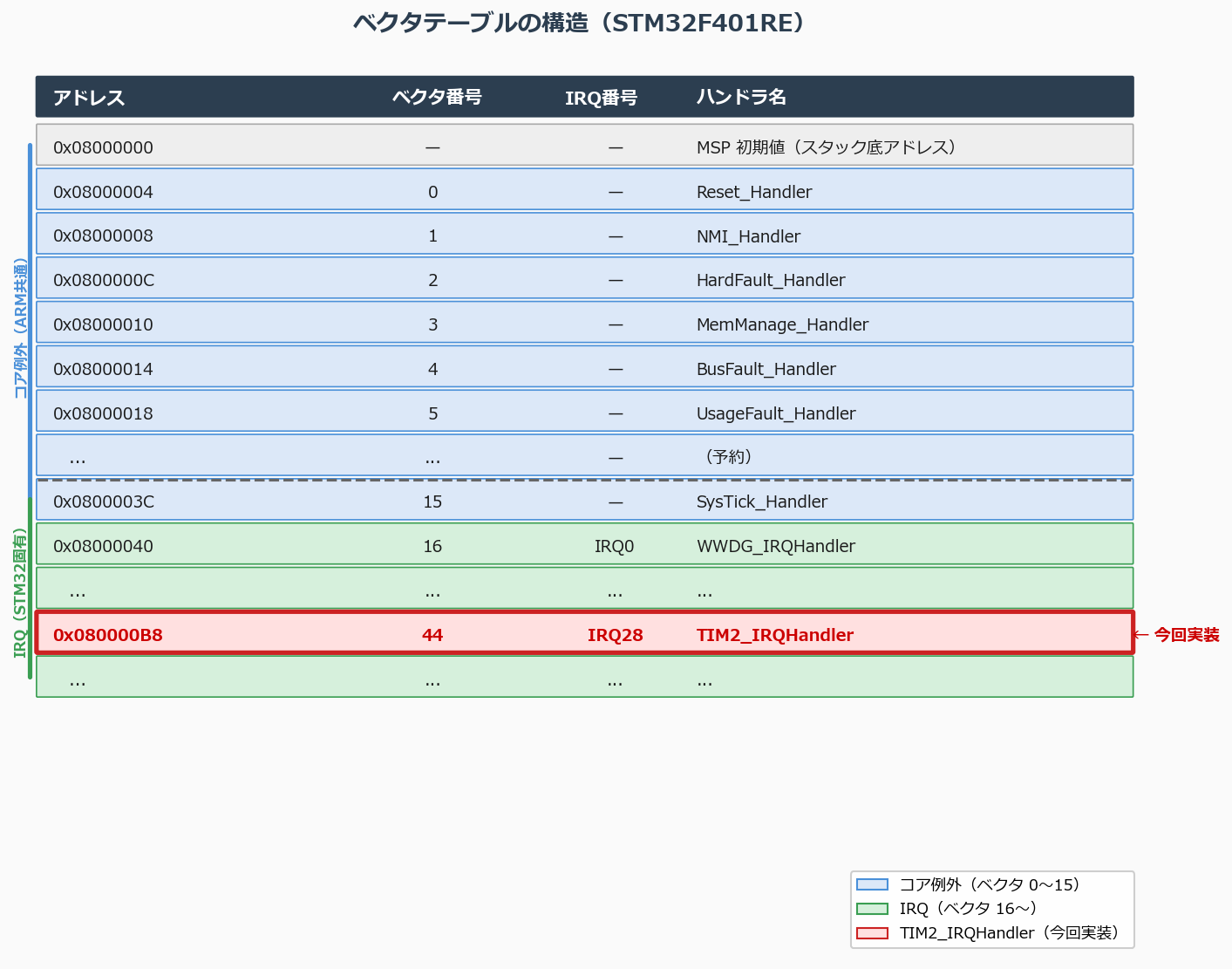
Vector table structure. Core exceptions (0–15) and IRQs (16+) are laid out consecutively. Each entry is a 4-byte ISR address.
🔧 NVIC — The Priority and Permission Manager
What is NVIC?
The NVIC (Nested Vectored Interrupt Controller) is a hardware module built into Cortex-M that handles interrupt priority management, enabling, disabling, and pending-bit clearing.
“Which interrupts are allowed?” “When multiple interrupts arrive simultaneously, which runs first?” — the NVIC decides all of this. The NVIC is also a scheduler that determines which interrupt runs and when.
NVIC is a name specific to ARM Cortex-M. Other MCUs always have hardware for managing interrupts, but under different names with different APIs.
| MCU | Interrupt management | Priority setting |
|---|---|---|
| STM32 (Cortex-M) | NVIC (ARM standard) | NVIC_SetPriority() |
| AVR (ATmega) | SREG I-bit (global enable only) | No priority (vector number order) |
| ESP32 (Xtensa) | INTC (Interrupt Controller) | esp_intr_alloc() with level |
| Renesas RA (Cortex-M) | NVIC (same ARM core) | Same API as STM32 |
| PIC | PIE/PIR registers + IPR | HIGH/LOW two levels |
Some MCUs (like AVR) have no priority concept at all — lower vector number wins. Others like STM32 let you set fine-grained numeric priorities. Either way, “allow or deny” and “which runs first” are universal roles.
How Priority Works
The STM32F401RE uses 4 bits (0–15) to set priority. Lower number = higher priority.
Priority 0  ← Strongest (can preempt any other ISR)
Priority 1
...
Priority 15 ← Weakest (preempted by everything)
Remember: “0 is strongest, 15 is weakest.” Many CPUs use the opposite convention (higher number = higher priority), so this is a classic source of configuration bugs on STM32.
STM32’s NVIC separates “preemption priority” from “subpriority.”
Interrupts with different preemption priorities can nest — the higher-priority ISR can preempt the lower one.
Subpriority determines execution order among interrupts sharing the same preemption priority (no nesting).
HAL defaults to using all 4 bits for preemption priority (NVIC_PRIORITYGROUP_4).
What Happens When Multiple Interrupts Overlap
“If a low-priority interrupt arrives while a high-priority ISR is running, does it get cancelled?” — a critical question. The answer is no.
The NVIC records every interrupt arrival as a Pending bit. Even if the interrupt can’t be handled immediately, the “it arrived” fact stays in the flag and will execute as soon as conditions allow.
Case 1: High-priority interrupt arrives during a low-priority ISR (Preemption)
Low-priority ISR (priority 2) running
        ↓
High-priority interrupt (priority 0) fires!
        ↓
Suspend low-priority ISR → save state to stack (context saving)
        ↓
Execute high-priority ISR (priority 0)
        ↓
High-priority ISR returns
        ↓
Resume low-priority ISR (restore state from stack)
        ↓
Low-priority ISR returns → back to main()
This is called preemption — the high-priority interrupt doesn’t wait for the low-priority ISR to finish. Because ISRs nest, stack consumption requires attention.
How the stack builds up during nesting:
← SP"] end subgraph s2["② Low-priority ISR fires"] direction TB B2["8 registers saved (32 bytes)
← SP"] A2["main local variables"] B2 --- A2 end subgraph s3["③ High-priority ISR preempts"] direction TB C3["8 registers saved (+32 bytes)
← SP (current)"] B3["Low-priority ISR save area (32 bytes)"] A3["main local variables"] C3 --- B3 --- A3 end s1 -->|"low-priority interrupt"| s2 s2 -->|"high-priority interrupt"| s3
Each context save consumes at least 32 bytes (8 registers × 4 bytes). If the ISR also uses R4–R11, it’s more. Deeper nesting = more stack consumed.
What happens when the stack is full (stack overflow):
The STM32F401RE’s stack size is determined by the linker script, defaulting to 0x200 (512 bytes). Too-deep nesting or large ISR local variables causes the stack to overwrite other memory regions (globals, heap).
When a stack overflow occurs:
  → Global variables are silently corrupted (hard to notice)
  → Eventually HardFault or MPU Fault fires and halts execution
  → Debugging becomes very difficult (the crash site and the cause are far apart)
Minimizing preemption-allowed priority combinations is the golden rule. Practical guidelines:
- Keep nesting depth to 2–3 levels max
- Keep ISR local variables small (never declare large buffers inside an ISR)
- To increase stack size, modify
_Min_Stack_Sizeinstartup_stm32f401retx.s - Under FreeRTOS or any RTOS, each task also needs its own independent stack
“Keep ISRs short” matters for stack consumption too.
Case 2: Low-priority interrupt arrives during a high-priority ISR (Pending)
High-priority ISR (priority 0) running
        ↓
Low-priority interrupt (priority 2) fires!
        ↓
NVIC sets the Pending bit (just records "it arrived")
High-priority ISR continues uninterrupted
        ↓
High-priority ISR returns
        ↓
NVIC detects Pending bit → executes low-priority ISR
        ↓
Low-priority ISR returns → back to main()
The low-priority interrupt is not cancelled — it stays pending and executes automatically as soon as the high-priority ISR finishes.
Case 3: Same-priority interrupts overlap
Same-priority interrupts cannot preempt each other. The later arrival stays Pending until the running ISR finishes. Which runs first is determined by vector number (lower = higher priority).
| Situation | What happens to the lower-priority interrupt |
|---|---|
| Low-priority fires during high-priority ISR | Pending → runs after high-priority ISR finishes |
| High-priority fires during low-priority ISR | Immediate preemption |
| Same-priority fires during same-priority ISR | Pending → runs after current ISR finishes |
If you forget to clear the timer or UART interrupt flag inside the ISR, the NVIC immediately re-invokes the ISR the instant it returns, thinking “the flag is still set.” The ISR repeats forever and main() never runs again.
When “main() doesn’t seem to run,” always check flag-clearing inside ISRs first.
NVIC Operations (CMSIS API)
/* NVIC functions provided by CMSIS */

/* ① Set priority */
NVIC_SetPriority(TIM2_IRQn, 1);   /* Set TIM2 to priority 1 */

/* ② Enable interrupt */
NVIC_EnableIRQ(TIM2_IRQn);        /* Allow TIM2 IRQ in NVIC */

/* ③ Disable interrupt */
NVIC_DisableIRQ(TIM2_IRQn);

/* ④ Clear pending interrupt */
NVIC_ClearPendingIRQ(TIM2_IRQn);
CubeMX-generated code uses the HAL_NVIC_xxx family:
HAL_NVIC_SetPriority(TIM2_IRQn, 1, 0);   /* preemption=1, sub=0 */
HAL_NVIC_EnableIRQ(TIM2_IRQn);
Internally these call CMSIS NVIC_SetPriority() / NVIC_EnableIRQ(). Both approaches produce identical results.
Global Interrupt Mask (enable/disable everything)
Separate from per-IRQ NVIC settings, there’s a global mask for all CPU interrupts:
__disable_irq();   /* PRIMASK = 1: disable all interrupts */
/* critical section, measurement, etc. */
__enable_irq();    /* PRIMASK = 0: re-enable interrupts */
As mentioned in Episode 7, while __disable_irq() is active, SysTick is also stopped, which means HAL_Delay() will infinite-loop. Keep critical sections minimal (a few µs at most) and do not call any code that depends on HAL_Delay / HAL_GetTick inside them.
🗂️ Context Saving — What the CPU Does Automatically
“Everything needed to pause and resume cleanly”
When an interrupt fires, the CPU suspends the current task and jumps to the ISR. To resume exactly where it left off after the ISR returns, the CPU must completely save its state at the moment of interruption.
This is context saving.
Registers Cortex-M saves automatically
At interrupt time, Cortex-M hardware automatically pushes these 8 registers onto the stack:
Registers pushed to stack on interrupt (hardware-automatic):

Stack (RAM)          Register    Description
+------------------+
| xPSR             |   Program Status Register (flags)
| PC (Return addr) |   Address of suspended instruction (resume point)
| LR               |   Link Register (caller address)
| R12              |   General-purpose register
| R3               |   General-purpose register
| R2               |   General-purpose register
| R1               |   General-purpose register
| R0               |   General-purpose register  ← SP points here
+------------------+
(older contents below)
When the ISR returns, the CPU automatically restores all of these, and the program counter (PC) resumes execution from the saved address.
There is a rule about who is responsible for each register.
- R0–R3, R12 — “Caller-saved” registers: the caller (main) accepts they may be clobbered. Hardware saves these automatically on interrupt entry.
- R4–R11 — “Callee-saved” registers: if the ISR uses them, it is responsible for preserving them. The compiler automatically generates prologue code to push them to the stack at the ISR’s start, and epilogue code to restore them at the end — but only if the ISR actually uses those registers.
The principle: “don’t save what you don’t use” — unnecessary stack operations are eliminated. Combined with the hardware’s 8-register save, the pre-interrupt state is fully restored.
The Cost of Context Saving
How many cycles does this stack operation take? You can measure it with DWT CYCCNT from Episode 7.
On the STM32F401RE (84 MHz), interrupt entry overhead is typically 12 to tens of cycles (roughly 0.14 to a few µs). Keeping this number in mind helps when reasoning about ISR execution time.
Interrupt entry breakdown:
  ① NVIC detects interrupt               a few cycles
  ② Hardware saves 8 registers to stack  ~8–12 cycles
  ③ Read vector table                    1 to a few cycles
  ④ Jump to ISR                          1 cycle
  Total: at minimum ~12–16 cycles
  * Flash wait states, cache state, bus contention can push this to tens of cycles
Because of context-saving overhead, an ISR that does too little work makes the overhead dominate — a case of the cure being worse than the disease. But an ISR that does too much will miss the next interrupt deadline. The golden rule is “set a flag, hand the work to the main loop” — keep heavy processing out of ISRs. Episode 9’s anti-pattern collection digs into this.
Tail-Chaining and Late Arrival (Cortex-M speed optimizations)
Cortex-M has two hardware optimizations that accelerate interrupt handling. Worth knowing so that real measurements make intuitive sense.
Tail-Chaining
If another interrupt is Pending at the moment one ISR finishes, rather than popping the stack and immediately pushing it again, the CPU skips the stack round-trip and jumps directly to the next ISR.
Without tail-chaining:
  ISR-A done → pop stack (8 regs) → ISR-B starts → push stack (8 regs)

With tail-chaining:
  ISR-A done → jump directly to ISR-B (no stack operation)
Back-to-back interrupts switch in as few as 6 cycles — useful when TIM2 at 1ms and UART receive fire consecutively.
Late Arrival
If a higher-priority interrupt arrives while the CPU is still in the middle of saving context (hasn’t entered any ISR yet), it redirects the jump to the higher-priority ISR. No re-saving cost — the higher-priority ISR starts at maximum speed.
These happen automatically; you don’t need to think about them. But when multiple interrupts are queued and processing is faster than you expected, this mechanism is why.
⏰ Implementing TIM2 Interrupts
Overview: Generating a 1ms periodic interrupt with TIM2
The implementation sequence:
① Configure TIM2 (prescaler, counter limit)
② Enable TIM2 interrupt (UEV: Update Event)
③ Register TIM2_IRQn in NVIC, set priority
④ Start TIM2
⑤ Write TIM2_IRQHandler()
⑥ Clear the interrupt flag (critical!)
How TIM2 Works
TIM2 is a 16/32-bit up-counter. It increments by 1 on each clock edge. When it reaches the configured limit (ARR: Auto-Reload Register), a UEV (Update Event) fires and the counter resets to 0.
TIM2 counter behavior:

0 → 1 → 2 → ... → ARR → (UEV fires, interrupt!) → 0 → 1 → ...
                                                    ↑
                                               ISR runs here
Period formula:
T_{period} = \frac{(\text{PSC} + 1) \times (\text{ARR} + 1)}{f_{TIM}}- PSC: Prescaler value (divides TIM2 clock)
- ARR: Auto-reload value (count limit)
- f_TIM: Clock frequency supplied to TIM2
Recall the clock tree from Episode 7. TIM2 is on the APB1 bus. With F401RE defaults, APB1 clock is 42 MHz. However, when the APB1 prescaler is not 1, the timer clock is 2× the APB1 clock (= 84 MHz). This is STM32-specific timer behavior, not a Cortex-M4 core rule — behavior differs on other ARM MCUs, so always check the reference manual when porting.
F401RE default settings (verify in CubeMX Clock Configuration tab):
- SYSCLK: 84 MHz
- APB1 prescaler: /2 → APB1 clock: 42 MHz
- TIM2 clock: 42 × 2 = 84 MHz
CubeMX Clock Configuration tab. Confirm that APB1 Timer clocks shows 84 MHz.
Calculating Parameters for 1ms Period
The timer period is determined by:
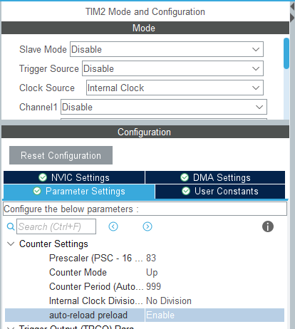
T_{period} = \frac{(\text{PSC}+1) \times (\text{ARR}+1)}{f_{TIM}}Substituting the values from CubeMX Parameter Settings:
| CubeMX field | Value | Meaning |
|---|---|---|
| Prescaler (PSC) | 83 | Divide by 84 → TIM2 clock = 84 MHz ÷ 84 = 1 MHz |
| Counter Period (ARR) | 999 | 1 MHz × 1000 counts → UIF flag fires every 1 ms |
Exactly 1 ms. The +1 on PSC and ARR is because register values are 0-indexed counters (PSC=0 means divide-by-1, ARR=0 means overflow after 1 count).
Implementation (Direct Register Access)
/* Place in main.c USER CODE BEGIN PD */

/* DWT macros (from Episode 7) */
#define DWT_INIT() do { \
    CoreDebug->DEMCR |= CoreDebug_DEMCR_TRCENA_Msk; \
    DWT->CYCCNT = 0; \
    DWT->CTRL |= DWT_CTRL_CYCCNTENA_Msk; \
} while(0)
#define DWT_START()        (DWT->CYCCNT)
#define DWT_CYCLES(start)  (DWT->CYCCNT - (start))


/* Place in main.c USER CODE BEGIN 0 */

/* Flags shared from ISR to main (volatile required) */
volatile uint32_t g_tim2_tick = 0;       /* incremented every 1ms */
volatile uint32_t g_isr_cycle_count = 0; /* ISR execution cycles (for measurement) */

/* TIM2 interrupt handler */
void TIM2_IRQHandler(void)
{
    uint32_t isr_start = DWT_START();

    /* ① Clear interrupt flag (mandatory! Without this, ISR loops forever) */
    TIM2->SR &= ~TIM_SR_UIF;

    /* ② Increment flag (let main do the heavy lifting) */
    g_tim2_tick++;

    /* ③ Measure ISR execution time (for debugging) */
    g_isr_cycle_count = DWT_CYCLES(isr_start);
}
/* Place in main.c USER CODE BEGIN 2 */

/* Initialize DWT (for measurement) */
DWT_INIT();

/* ─── TIM2 initialization (direct register access) ──────── */

/* ① Supply clock to TIM2 via RCC */
RCC->APB1ENR |= RCC_APB1ENR_TIM2EN;

/* ② Reset TIM2 to a known state */
TIM2->CR1 = 0;

/* ③ Prescaler: divide by 84 → TIM2 clock = 1 MHz */
TIM2->PSC = 84 - 1;   /* PSC = 83 */

/* ④ Auto-reload value: 1000 counts → 1ms period */
TIM2->ARR = 1000 - 1;   /* ARR = 999 */

/* ⑤ Enable UEV (Update Event) interrupt */
TIM2->DIER |= TIM_DIER_UIE;

/* ─── NVIC configuration ─────────────────────────────────── */

/* ⑥ Set TIM2 IRQ priority (0–15, lower = higher priority) */
NVIC_SetPriority(TIM2_IRQn, 1);

/* ⑦ Enable TIM2 IRQ in NVIC */
NVIC_EnableIRQ(TIM2_IRQn);

/* ─── Start TIM2 ──────────────────────────────────────────── */

/* ⑧ Set CEN bit to start TIM2 counting */
TIM2->CR1 |= TIM_CR1_CEN;
/* Place in main.c USER CODE BEGIN WHILE (inside while(1)) */

uint32_t last_tick = 0;

while (1)
{
    /* Wait for g_tim2_tick to change (process on main-loop side) */
    if (g_tim2_tick != last_tick)
    {
        last_tick = g_tim2_tick;

        /* This runs every 1ms */
        HAL_GPIO_TogglePin(GPIOA, GPIO_PIN_5);   /* Toggle LD2 (PA5) */
    }
}
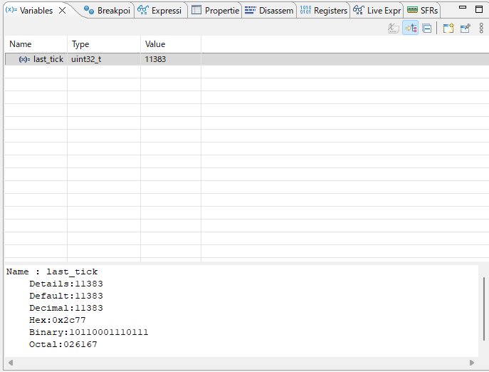
Watching g_tim2_tick increment in the debugger. After 1 second, it should read approximately 1000.
Comparison: HAL Version
Using CubeMX, the same functionality looks like this:
/* HAL version (using CubeMX-generated code) */

/* Code auto-generated in MX_TIM2_Init() */
htim2.Instance = TIM2;
htim2.Init.Prescaler = 84 - 1;
htim2.Init.CounterMode = TIM_COUNTERMODE_UP;
htim2.Init.Period = 1000 - 1;
htim2.Init.ClockDivision = TIM_CLOCKDIVISION_DIV1;
HAL_TIM_Base_Init(&htim2);

/* USER CODE BEGIN 2 */
HAL_TIM_Base_Start_IT(&htim2);   /* Start TIM2 with interrupt */

/* TIM2_IRQHandler in stm32f4xx_it.c (auto-generated) */
void TIM2_IRQHandler(void)
{
    HAL_TIM_IRQHandler(&htim2);   /* Flag clearing handled internally */
}

/* Callback — write this yourself */
void HAL_TIM_PeriodElapsedCallback(TIM_HandleTypeDef *htim)
{
    if (htim->Instance == TIM2)
    {
        g_tim2_tick++;   /* Called every 1ms */
    }
}
HAL_TIM_Base_Start_IT() also handles NVIC configuration internally. However, the NVIC priority must be set beforehand in CubeMX’s “NVIC Settings” tab. Understanding the register-level version first makes HAL usage far more productive — you’ll know exactly what HAL is doing under the hood when things go wrong.
Verifying the Result
Watch g_tim2_tick in the debugger and wait 1 second — it should read approximately 1000, confirming near-exact 1ms precision.
Checking g_isr_cycle_count reveals the ISR body’s cycle count (flag clear + counter increment):
g_isr_cycle_count ≈ 8–12 cycles (~0.1–0.15 µs)

Including interrupt entry overhead:
Total interrupt processing ≈ 20–30 cycles (~0.25–0.36 µs)
As a fraction of 1ms = 84,000 cycles: interrupt cost ≈ 0.03%
For a 1ms period (84,000 cycles), an interrupt overhead under 30 cycles is negligible. That said, for high-frequency interrupts (period below tens of µs) or RTOS environments, the overhead becomes non-trivial.
Omitting TIM2->SR &= ~TIM_SR_UIF; causes a new interrupt to fire the instant the ISR returns, creating an infinite loop the CPU cannot escape from. Always verify flag clearing is present before anything else when writing interrupt handlers.
In the HAL version, HAL_TIM_IRQHandler() handles flag clearing internally.
The code example clears the flag at the top. “Shouldn’t I clear it at the end after I’m done?” — placing it at the end is dangerous.
In STM32, there are a few CPU cycles of bus-access latency between writing the clear instruction and the hardware actually reflecting it. If you clear at the end, the ISR may return before the clear takes effect. The NVIC then sees “flag still set” and immediately re-invokes the ISR. This is especially likely in fast-clock, low-latency environments like STM32F4 at 84 MHz.
“Clear first, then process” eliminates the double-entry risk entirely — and as a bonus, makes forgetting the clear far more obvious.
⚠️ Shared Variables in ISRs (volatile and a Teaser for Next Time)
Why is volatile required?
Did you notice the volatile on g_tim2_tick?
volatile uint32_t g_tim2_tick = 0; /* volatile is mandatory */
Recall the optimization bug from Episode 6. Without volatile, at -O2 optimization:
Inside main()'s while(1) loop:

At -O0:
  Reads g_tim2_tick from RAM every iteration → sees ISR changes ✅

At -O2:
  Compiler sees "no code in this loop modifies g_tim2_tick"
  → reads it once into a register and caches it there forever
  → ISR writes to RAM, but main never re-reads → infinite loop ❌
volatile tells the compiler “this memory can change at any time without my knowledge.” Apply it to any variable written by an ISR, DMA, or hardware peripheral.
Atomicity (teaser for next time)
But volatile alone is sometimes not enough:
/* ❌ A 32-bit variable read/write may not be atomic (multi-byte update concern) */
volatile uint32_t g_sensor_value = 0;

/* Inside ISR */
void TIM2_IRQHandler(void) {
    TIM2->SR &= ~TIM_SR_UIF;
    g_sensor_value = read_sensor();   /* 32-bit write */
}

/* In main */
uint32_t val = g_sensor_value;   /* 32-bit read */
/* ← What if the ISR write and this read overlap? */
The Cortex-M4 is a 32-bit CPU, so reading or writing an aligned uint32_t completes in one instruction (LDR/STR) — one instruction cannot be interrupted midway. That’s the physical meaning of atomic. Think of it the same way as “the weight of one cycle” from Episode 7: “a 32-bit CPU moves 32 bits in one shot.” “Aligned” means the address is a multiple of 4, which compilers guarantee automatically for normal global and local variables.
However, 64-bit variables, structs, or updating multiple variables together cannot be done in a single instruction and are not atomic.
/* ❌ Updating multiple variables "together" — an ISR can slip in between */
volatile uint32_t g_timestamp = 0;
volatile uint32_t g_value = 0;

/* In ISR */
g_timestamp = current_time;   /* ← ISR could be interrupted here */
g_value = new_value;           /* main reads only the new timestamp with old value */
Preventing this requires a critical section (interrupt-disabled region). Episode 9’s anti-pattern collection covers this thoroughly.
volatile on variables shared between an ISR and main is mandatory — but it alone does not guarantee atomicity (freedom from mid-operation interruption). Single uint32_t reads/writes are atomic on Cortex-M4, but when you need multiple variables to update as a consistent unit, a critical section is required.
Summary
Key takeaways from this episode:
- Limits of polling → Monopolizes CPU, poor precision, breaks as tasks grow
- Interrupt fundamentals → Hardware forces CPU to “handle this now”
- Vector table → An array of ISR addresses at the start of Flash; the CPU reads it on every interrupt
- NVIC → Hardware controller managing priority, enable, and pending-clear
- Context saving → CPU automatically pushes 8 registers to stack on interrupt, restores them on return
- TIM2 implementation → Set period with PSC/ARR, never forget to clear the UIF flag
- volatile requirement → Any variable shared with an ISR must be
volatile
Interrupts feel “scary” because you never know exactly when the ISR will preempt your code. Follow these principles and you can keep them under control.
- Keep it short — ISR execution must finish before the next interrupt deadline
- Minimize side effects — Write as little as possible to globals; prefer flag-based notification
- Protect shared variables —
volatilefor ISR-shared variables; critical sections when updating multiple variables as a unit
Next time we’ll deliberately break these principles to see what happens.
An interrupt is not “a convenient function call” — it is “an asynchronous intruder from a parallel world.” Whether you truly internalize this distinction is the dividing line between embedded engineers.
Next up: “Interrupt Design Anti-Pattern Collection” — doing printf in an ISR, putting heavy processing in an ISR, forgetting volatile. We’ll deliberately trigger these common landmines and watch things break.
What’s Next
🔥 Episode 9: Interrupt Design Anti-Patterns [Critical]
Heavy processing in ISRs, printf (fatal), sloppy shared-variable access, volatile overuse/underuse… we'll deliberately trigger every classic landmine and watch systems break — the pivotal episode separating strong from weak embedded engineers.
📖 Read Episode 9FAQ
Q. Should I use interrupts or polling?
Use interrupts when timing precision matters (µs level) or when you need to run tasks in parallel. Polling is fine when timing doesn’t need to be exact and simplicity is a priority. “Avoid interrupts if you can get away without them” is a valid design heuristic.
Q. Can I call printf (UART send) from inside an ISR?
Principally no. UART transmission tends to be blocking, making the ISR take much longer and blocking other interrupts. HAL UART functions also use internal wait loops, which can cause deadlocks inside an ISR. Use LED toggling or DWT-based measurement for debug output instead. Episode 9 covers this in detail.
Q. My interrupt won’t stop (can’t return to main()) — what’s wrong?
Almost always a forgotten flag clear inside the ISR. Check that you have TIM2->SR &= ~TIM_SR_UIF; (or equivalent) at the top of your ISR.
Q. What priority value should I use?
Start with 1 (fairly high). SysTick (used by HAL) defaults to priority 0, so setting TIM2 to 0 risks competing with it. Priority 1 or higher is the safe default.
Q. HAL or direct register access — which should I use?
In production, HAL is safer and more maintainable. But writing the register version by hand at least once gives you an understanding of what HAL is doing internally, which dramatically improves debugging ability when things go wrong.
![[STM32 Series #9] Interrupt Design Anti-Patterns — Learn ISR Pitfalls by Deliberately Breaking Things](/posts/stm32-episode09/thumbnail.jpg)