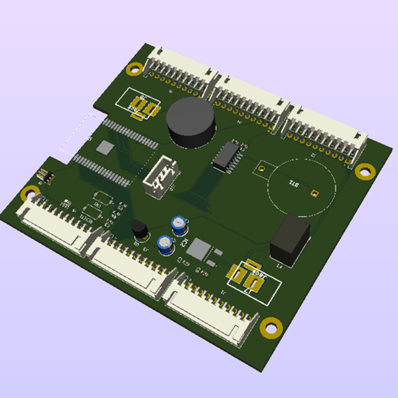
Introduction
Build anything of reasonable size on an ESP32 or Arduino and you eventually hit the same wall: you run out of pins. You want to drive a lot of LEDs, you have too many switches to read, you need to hang several sensors off one board. That is where an I/O expander earns its place.
This article covers the MCP23017, which adds 16 pins over I2C, with a schematic and a working circuit. Sample code for the current Adafruit_MCP23X17 library is included, so you can get something running right away.
What you will learn
- How the MCP23017 works, its specifications, and its pin assignments
- I2C address selection and running multiple devices (up to 8 chips, 128 pins)
- A worked MCP23017 circuit with a schematic (8 LED outputs and 3 switch inputs)
- How to use the current Adafruit_MCP23X17 library, with sample code
- Programming patterns for input and output, plus troubleshooting
What Is the MCP23017? Why GPIO Expansion Matters
Why you need an I/O expander
Microcontroller projects run short of pins in a few predictable places:
- Driving LEDs: LED matrices and seven-segment displays eat pins quickly
- Reading switches: buttons and sensor inputs add up
- Combined projects: a display plus sensors plus a motor, all at once
An I/O expander solves this cleanly by splitting the work:
| Job | Where it belongs |
|---|---|
| Plain digital input and output | The I/O expander (MCP23017) |
| A/D conversion, PWM | The microcontroller’s own pins |
Reserve the MCU’s pins for the things only the MCU can do, and push the simple on/off work out to the expander.
About the part
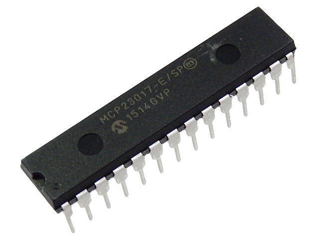
MCP23017 in a 28-pin DIP package
The MCP23017 is a 16-bit I/O GPIO expander from Microchip Technology. It is controlled over I2C, which makes it a natural fit for the ESP32 and for Arduino boards.
Specifications and Circuit Design
Reading the datasheet
MCP23017 datasheet (Microchip)
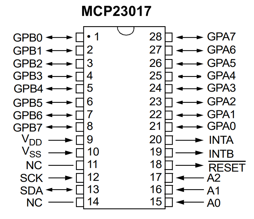
MCP23017 pin assignments
Key specifications
| Item | Specification |
|---|---|
| Interface | I2C (supports 400 kHz) |
| Supply voltage | 1.8 V to 5.5 V (works at the ESP32’s 3.3 V) |
| I/O pins | 16 (GPA0–GPA7 / GPB0–GPB7) |
| Maximum drive current | 25 mA per pin |
| Devices per bus | Up to 8 (selected by I2C address) |
How the I2C address is selected
The MCP23017 has three address pins (A0, A1, A2). Their combination lets you put up to eight devices on a single I2C bus.
Address table
| A2 | A1 | A0 | I2C address | Legacy library index (not used today) |
|---|---|---|---|---|
| 0 | 0 | 0 | 0x20 | 0 (default) |
| 0 | 0 | 1 | 0x21 | 1 |
| 0 | 1 | 0 | 0x22 | 2 |
| 0 | 1 | 1 | 0x23 | 3 |
| 1 | 0 | 0 | 0x24 | 4 |
| 1 | 0 | 1 | 0x25 | 5 |
| 1 | 1 | 0 | 0x26 | 6 |
| 1 | 1 | 1 | 0x27 | 7 |
The value you pass depends on which generation of the library you are using.
- Current
Adafruit_MCP23X17: pass the I2C address itself (0x20–0x27), as inmcp.begin_I2C(0x20). This is what the sketch in this article does. - Legacy
Adafruit_MCP23017: took an index from 0 to 7 instead. The last column is kept only as a lookup for when you run into older articles or code.
For anything you write today, use the I2C address column, not the 0–7 index.
A0 through A2 must each be tied to either 0 (GND) or 1 (VDD). Leaving them unconnected is not a valid “0” — a floating pin picks up noise and the chip may answer at an unpredictable address, or not at all.
The headline number: 128 pins
- One MCP23017 → 16 pins
- Eight of them → 128 pins
That is enough headroom that pin count stops being a design constraint for almost any hobby project.
Other features worth knowing
- Internal pull-ups: a 100 kΩ pull-up can be enabled per pin
- Interrupt output: the chip can notify the MCU when an input changes state, so you do not have to poll
- Port-wide access: all 8 bits of a port can be read or written in one operation
Example Circuit: Switch Inputs and LED Outputs
Circuit overview
To exercise the chip, I built the following:
- Inputs: 3 switches (GPB0–GPB2)
- Outputs: 8 LEDs (GPA0–GPA7)
- Address: A0, A1 and A2 all tied to GND (address 0x20)
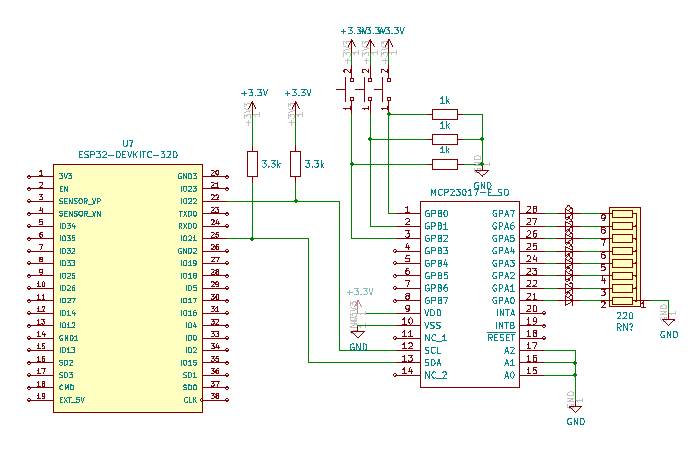
MCP23017 test circuit schematic
Points to note in the schematic
- Address pins: A0, A1 and A2 are pulled down to GND through resistors
- Switch inputs: each switch has a pull-down resistor, so pressing it drives the input HIGH
- LED outputs: each LED goes through a current-limiting resistor
On the breadboard
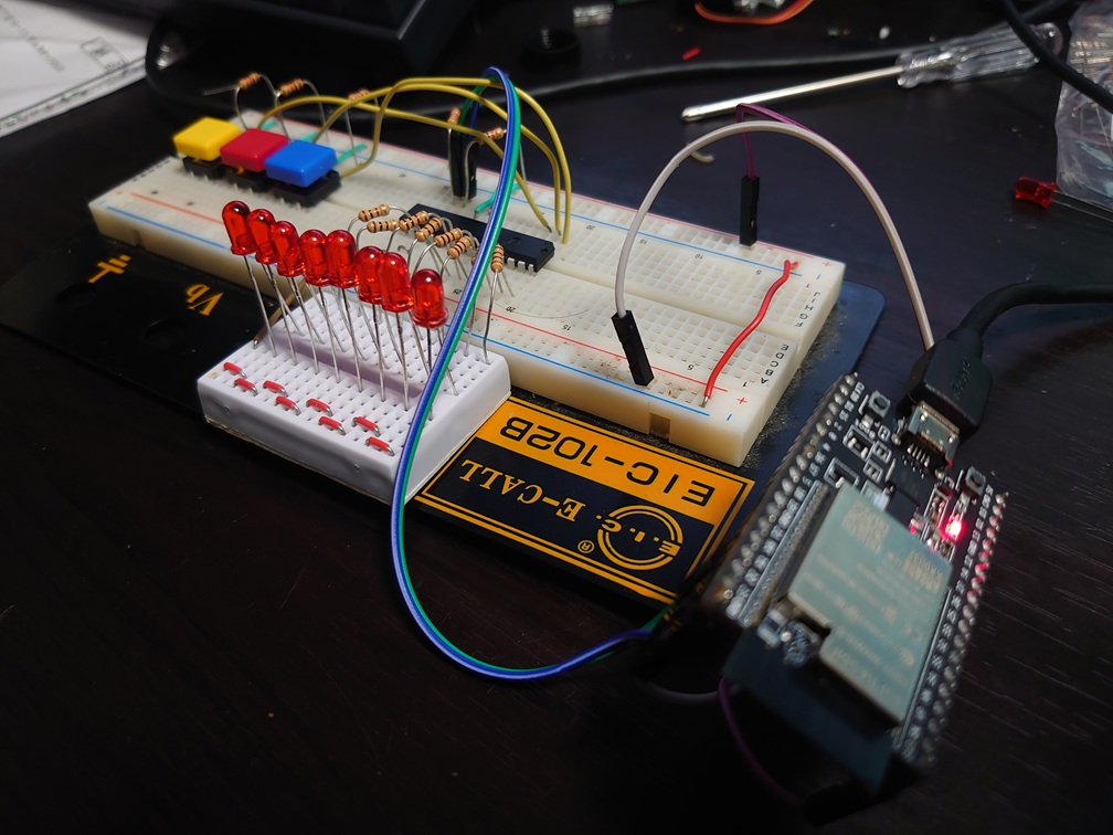
The circuit built on a breadboard
Wiring to the ESP32
| ESP32 | MCP23017 |
|---|---|
| 3.3 V | VDD |
| GND | VSS, A0, A1, A2 |
| GPIO21 (SDA) | SDA |
| GPIO22 (SCL) | SCL |
Both SDA and SCL need a pull-up resistor to VDD — around 4.7 kΩ is a good starting point. I2C outputs are open-drain: the devices on the bus can only pull the line low, so without pull-ups nothing ever returns to the HIGH state and the bus simply does not work.
Setting Up the Adafruit_MCP23X17 Library
Installing
In the Arduino IDE, open the Library Manager, search for “Adafruit MCP23017”, and install the Adafruit MCP23XXX library.
Library Manager → "Adafruit MCP23XXX" → Install
Dependencies
The library pulls in the following automatically:
- Adafruit BusIO
- Wire (bundled with the IDE)
Sample Program: Switching LED Patterns
The full sketch
#include <Wire.h>
#include <Adafruit_MCP23X17.h>

Adafruit_MCP23X17 mcp;

int sw1, sw2, sw3;

void setup() {
  delay(1000);
  Serial.begin(115200);

  // Initialize the MCP23017
  if (!mcp.begin_I2C(0x20)) {  // initialize at address 0x20
    Serial.println("MCP23017 not found!");
    while (1);
  }
  Serial.println("MCP23017 initialized");

  // Configure GPA0-GPA7 as outputs (LEDs)
  for (int i = 0; i < 8; i++) {
    mcp.pinMode(i, OUTPUT);
  }

  // Configure GPB0-GPB2 as inputs (switches)
  mcp.pinMode(8, INPUT);
  mcp.pinMode(9, INPUT);
  mcp.pinMode(10, INPUT);

  delay(1000);
}

void loop() {
  // Read the switch states
  sw1 = mcp.digitalRead(8);
  sw2 = mcp.digitalRead(9);
  sw3 = mcp.digitalRead(10);

  Serial.print("SW1:"); Serial.print(sw1);
  Serial.print(" SW2:"); Serial.print(sw2);
  Serial.print(" SW3:"); Serial.println(sw3);

  // Change the LED pattern based on the switch combination
  if (sw1 == 1 && sw2 == 0 && sw3 == 0) {
    // Mode 1: first four LEDs on
    Serial.println("Mode 1: Front LEDs ON");
    for (int i = 0; i < 4; i++) mcp.digitalWrite(i, HIGH);
    for (int i = 4; i < 8; i++) mcp.digitalWrite(i, LOW);

  } else if (sw1 == 0 && sw2 == 1 && sw3 == 0) {
    // Mode 2: last four LEDs on
    Serial.println("Mode 2: Back LEDs ON");
    for (int i = 0; i < 4; i++) mcp.digitalWrite(i, LOW);
    for (int i = 4; i < 8; i++) mcp.digitalWrite(i, HIGH);

  } else if (sw1 == 0 && sw2 == 0 && sw3 == 1) {
    // Mode 3: all LEDs on
    Serial.println("Mode 3: All LEDs ON");
    for (int i = 0; i < 8; i++) mcp.digitalWrite(i, HIGH);

  } else {
    // Mode 0: all LEDs off
    Serial.println("Mode 0: All LEDs OFF");
    for (int i = 0; i < 8; i++) mcp.digitalWrite(i, LOW);
  }

  delay(100);
}
Adafruit_MCP23X17 Function Reference
-
mcp.begin_I2C(addr)— start I2C communication Opens the connection to the chip. Pass the device’s I2C address, which is one of 0x20 through 0x27 depending on how you wired A0–A2 (see the address table above). The sketch above usesmcp.begin_I2C(0x20)because all three address pins are tied to GND. The call returnsfalseif the chip does not answer, which is the first thing to check when nothing works. -
mcp.pinMode(pin, mode)— set the direction of a pin Pins are numbered 0–15: GPA0–GPA7 are 0–7, and GPB0–GPB7 are 8–15. PassOUTPUTorINPUTformode. Any pin can be either — in this project 0–7 happen to be outputs and 8–10 inputs, but that is a choice of the circuit, not a property of the chip. -
mcp.digitalRead(pin)— read an input Returns 1 when the pin is HIGH and 0 when it is LOW. -
mcp.digitalWrite(pin, val)— drive an output PassHIGH(1) to drive the pin high andLOW(0) to drive it low.
It in Action
Here is the circuit running:
The LED pattern follows the switch states in real time. That is the basic input and output path through the MCP23017 working end to end.
What each state does
- SW1 only: the first four LEDs (GPA0–GPA3) light up
- SW2 only: the last four LEDs (GPA4–GPA7) light up
- SW3 only: all eight LEDs light up
- No switch pressed: all LEDs off
Where 16 Extra Pins Come in Handy
A few project shapes that the MCP23017 fits well.
1. Large LED matrices
One MCP23017 can drive the rows and columns of an 8×8 LED matrix. Chain several and you can build a 16×16 display or larger.
2. Multi-button input panels
Manage up to 16 buttons or switches from a single chip. With the internal pull-ups enabled you do not even need external resistors.
3. Relay control boards
Switch eight relays to automate appliances or motors — a solid backbone for a smart-home project.
4. Sensor aggregation
Collect the inputs from several digital sensors (temperature/humidity, motion, door contacts) on the MCP23017 and keep the ESP32’s own pins free.
Troubleshooting
The MCP23017 is not detected
Symptom: begin_I2C() returns false
Check, in order:
- I2C pull-ups: 4.7 kΩ from SDA and SCL to VDD
- Supply voltage: confirm 3.3 V or 5 V is actually reaching VDD
- Address pins: A0, A1 and A2 wired correctly — floating is not acceptable
- Wiring: make sure SDA and SCL are not swapped
Confirm with an I2C scanner:
#include <Wire.h>
void setup() {
  Wire.begin();
  Serial.begin(115200);
  Serial.println("I2C Scanner");
  for (byte address = 1; address < 127; address++) {
    Wire.beginTransmission(address);
    if (Wire.endTransmission() == 0) {
      Serial.print("Device found at 0x");
      Serial.println(address, HEX);
    }
  }
}
void loop() {}
The LEDs do not light correctly
Check:
- Current-limiting resistors: 330 Ω, or whatever value suits your LEDs
- Current budget: the MCP23017 is rated for 25 mA per pin
- Code: confirm the pin really was set to
OUTPUTwithpinMode()
Switch inputs are unstable
What to do:
- Pull-up or pull-down: enable the internal pull-up with
pinMode(pin, INPUT_PULLUP) - Debouncing: add software debounce to reject contact chatter
- Wiring: make sure the input pin is not left floating
Using the MCP23017 with Other Microcontrollers
Because everything happens over I2C, the MCP23017 is not tied to the ESP32.
| Microcontroller | I2C pins | Notes |
|---|---|---|
| ESP32 | GPIO21 (SDA) / GPIO22 (SCL) | This article |
| Arduino Uno R4 | A4 (SDA) / A5 (SCL) | Arduino’s standard I2C pin pair |
| Raspberry Pi | GPIO2 (SDA) / GPIO3 (SCL) | Drive it from smbus2 or RPi.GPIO |
On a Raspberry Pi you would talk to the chip from Python using the smbus2 library. Run i2cdetect -y 1 and you should see an address in the 0x20–0x27 range; if you do, the wiring is good. The register-level operations (IODIR, GPIO) follow the datasheet, so the principle is identical no matter which host you use.
Summary
That is a complete pass over I/O expansion with the ESP32 and the MCP23017.
Key points
- The MCP23017 adds 16 pins over I2C — two wires, sixteen pins
- The current Adafruit_MCP23X17 library makes it straightforward to drive
- Up to 8 chips on one bus gives you 128 pins
- Internal pull-ups and interrupt output are there when you need them
- It covers a wide range of jobs: LED driving, switch input, sensor aggregation
Where to go next
- Put several MCP23017s on the same bus and control even more pins
- Use the interrupt output to move from polling to event-driven code
- Consider the MCP23S17, the SPI version, when you need more throughput
With an expander in your parts drawer, pin count stops dictating what you are allowed to build.
Happy hacking!
Related Articles
Start with the bus itself:
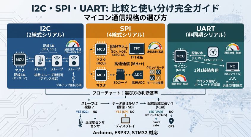
- I2C vs SPI vs UART: Wiring, Speed, and How to Choose: why the I2C addresses and pull-up resistors used here are necessary at all, compared against SPI and UART. Covers how to calculate the pull-up value (upper and lower bounds), and how the start condition and ACK work.
Other ways to expand your GPIO:
| Approach | Characteristics | Article |
|---|---|---|
| MCP23017 (I2C) | Simple wiring, several chips share two wires, up to 8 devices | This article |
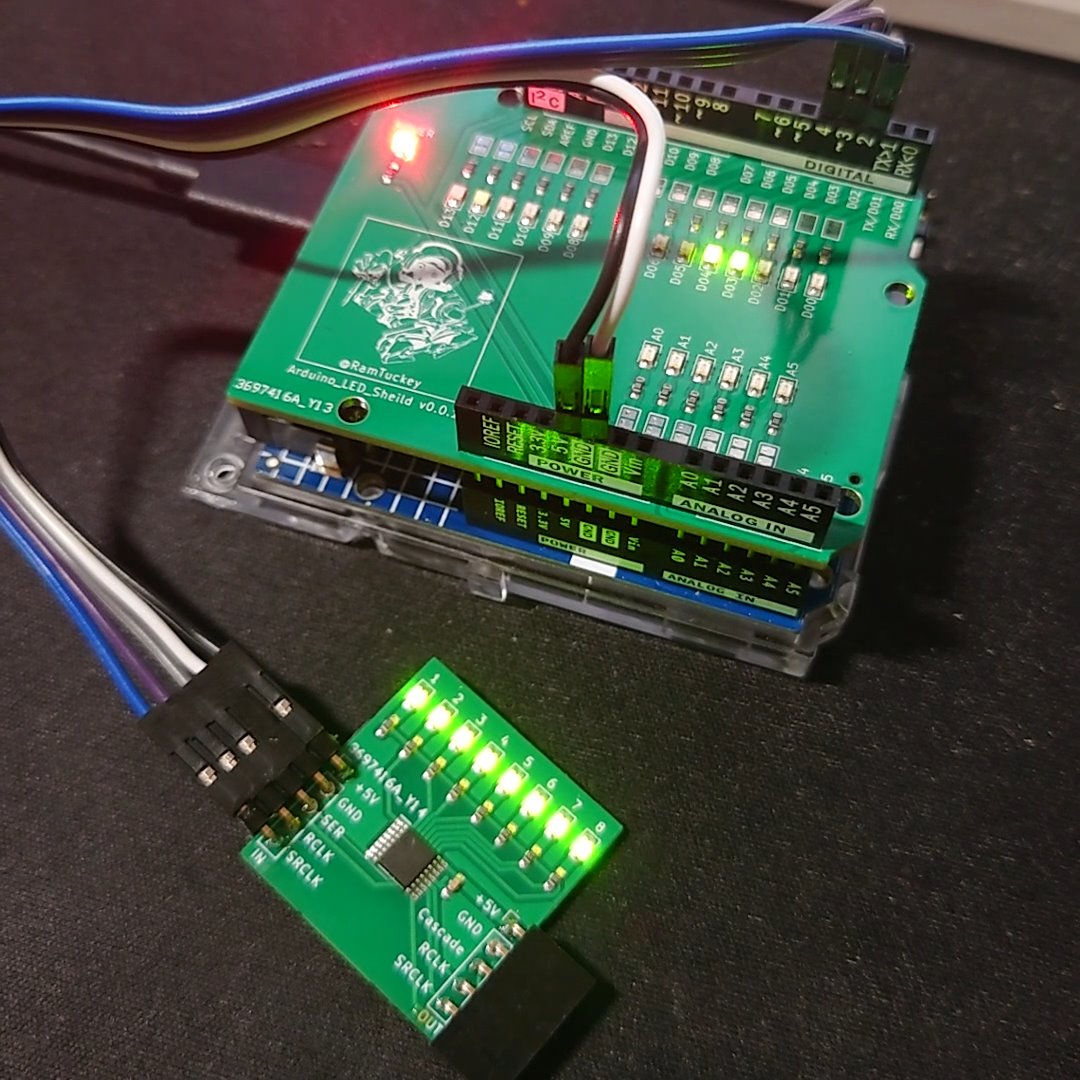
| 74HC595 (SPI) | Three signal lines, daisy-chainable without limit, fast | 74HC595 Complete Guide: Wiring and Arduino Code |
Worth reading alongside this:
- Arduino LED Circuit for Beginners: Ohm’s Law Resistor Calculation: how to size the current-limiting resistors on the eight LED outputs above, and why 25 mA per pin is a ceiling you should design well under.
- Arduino ADC Explained: Analog Input and Resolution: the MCP23017 is digital-only, so analog sensors still need the MCU’s own pins — this is the other half of the I/O picture.