Introduction
Lighting up an LED is the classic first step in electronics. It looks trivial, but getting the resistor value right requires Ohm’s Law — one of the most fundamental concepts in circuit design.
In this guide, we’ll calculate the correct resistor value from scratch, wire the circuit on a breadboard, and cover everything a beginner needs to succeed.
Why Start with an LED?
Every core concept in one circuit
An LED circuit is the smallest self-contained electronics project. Building one teaches you:
| Concept | What you learn |
|---|---|
| Voltage | The relationship between supply voltage and LED forward voltage (Vf) |
| Current | Controlling how much current flows through the LED |
| Resistance | Using a resistor to limit current |
| Ohm’s Law | Applying V = I × R in a real circuit |
Instant visual feedback
“It lit up!” is one of the best feelings in electronics. That immediate feedback builds confidence and motivates you to tackle more complex projects.
Components
| Component | Role | Spec |
|---|---|---|
| LED | Light source | Forward voltage Vf ≈ 2.1 V, max current 30 mA |
| Resistor | Current limiter | 330 Ω (E24 series, 1/4 W) |
| Power supply | Power | 9 V battery or DC adapter (5–12 V) |
| Breadboard | Prototyping board | No soldering required |
| Jumper wires | Wiring | Breadboard-compatible |
LED polarity
LEDs have a direction. The longer leg is the anode (+), the shorter leg is the cathode (−). Reversing them won’t damage the LED, but it won’t light up either.
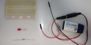
Components needed to light up an LED
Calculating the Resistor Value
The circuit
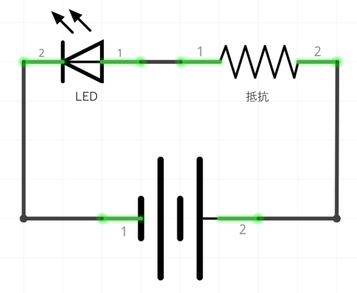
Basic LED circuit schematic
Ohm’s Law: R = V / I
We need a resistor in series to limit the current through the LED. Here’s the calculation step by step:
- Supply voltage: 9 V (battery)
- LED forward voltage: Vf = 2.1 V (at 20 mA)
- Voltage across the resistor: Vr = 9 V − 2.1 V = 6.9 V
- Target current: I = 20 mA = 0.02 A
R = Vr / I = 6.9 V / 0.02 A = 345 Ω
Choosing the nearest standard value
345 Ω doesn’t exist in the E24 resistor series. The closest standard value is 330 Ω.
Let’s verify the actual current with 330 Ω:
I = 6.9 V / 330 Ω = 0.021 A = 21 mA
21 mA is safely below the LED’s 30 mA maximum — ✅ safe to use.
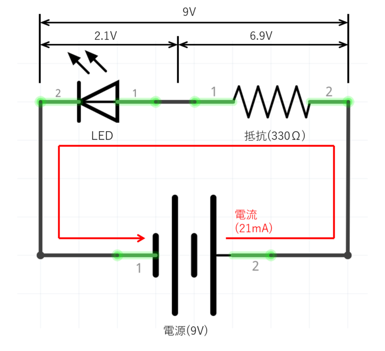
Actual current with a 330 Ω resistor
Wiring the Breadboard
Step-by-step
- Place the resistor: Insert the 330 Ω resistor into any row on the breadboard
- Place the LED: Connect the anode (long leg) to one end of the resistor; connect the cathode (short leg) to the GND rail
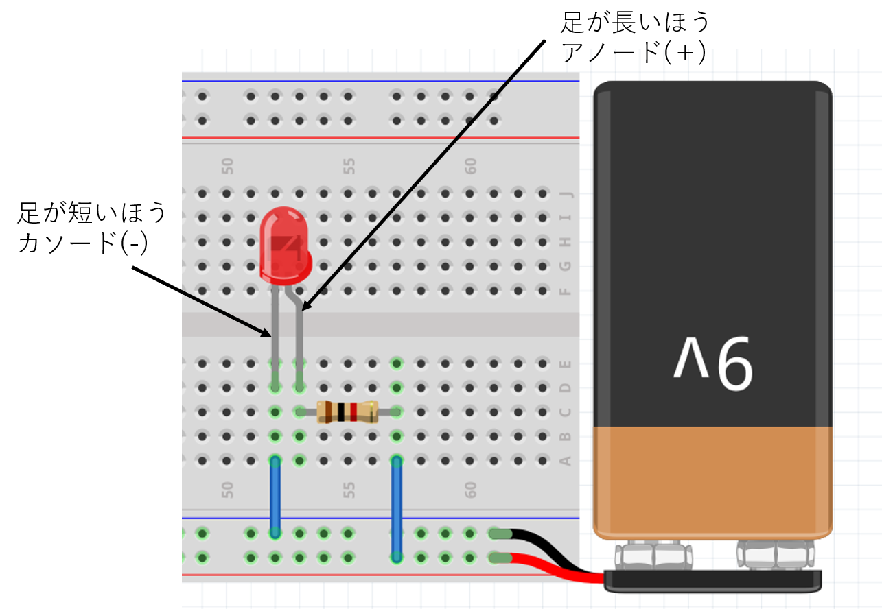
Breadboard layout
- Connect power: Connect the positive terminal of the battery to the resistor; connect the negative terminal to the GND rail
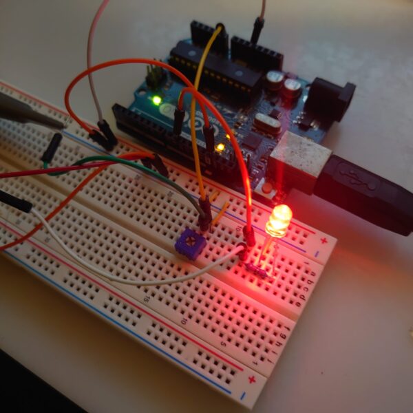
- Test it: Switch the power on — the LED should light up immediately
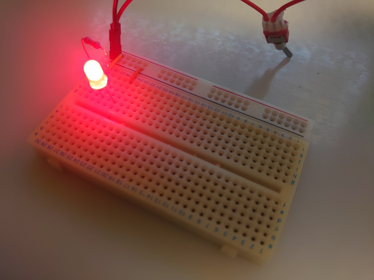
LED lit up on the breadboard
Troubleshooting
If the LED doesn’t light up, check the following:
- LED orientation: Is the anode connected toward the positive supply?
- Battery voltage: Test with a multimeter — a 9V battery below ~7V may not drive the LED
- Resistor value: Read the color bands — 330 Ω is orange-orange-brown
- Breadboard connections: Make sure the legs are fully inserted and in the correct rows
Going Further
Try different LED colors
Forward voltage varies by color — recalculate the resistor whenever you change colors:
| Color | Typical Vf |
|---|---|
| Red | ≈ 1.8 V |
| Green | ≈ 2.1 V |
| Blue | ≈ 3.2 V |
Control brightness with Arduino PWM
Once you have the LED wired, connect the resistor to one of Arduino’s PWM-capable pins (marked ~) and use analogWrite() to smoothly vary brightness from 0 to 255.
Add a sensor
Pair a photoresistor with your LED so it automatically turns on when the room gets dark — a classic beginner project that introduces analog input.
Summary
- Always use a current-limiting resistor in series with an LED
- Calculate resistor value: R = (Supply voltage − Vf) / target current
- 330 Ω is the right choice for a 9 V supply and a standard LED at 20 mA
- LED long leg = anode (+), short leg = cathode (−)
Related Articles
- Arduino UNO R4 Software PWM on Every Digital Pin: The natural next step after this guide — fade your LED smoothly with PWM.
- 74HC595 Complete Guide: Wiring and Arduino Code: Expand beyond Arduino’s pin count and drive LED arrays with a shift register.
- Arduino RGB LED PWM Control: 8 Colors to 16.7 Million: Apply the same resistor math per color channel and mix your own colors.
- Arduino ADC Explained: Analog Input and Resolution: Read a voltage instead of setting one — the input side of the same fundamentals.
- Arduino Piezo Buzzer: Play Music with the tone() Function: Swap the LED for a buzzer and turn the same output pin into sound.
- Arduino IR Remote: Receive and Decode with IRremote: Control the LED you just built from across the room with a TV remote.