This article contains affiliate links (Amazon Associates).
See It in Action First
Normally, an Arduino digital pin can only output HIGH (5V) or LOW (0V). In other words, an LED is either on or off — there is no in between.
But look at the video above. The LEDs fade in and out as if they were breathing. And not only on the PWM-capable pins (the ones marked with ~) — every single pin is glowing smoothly at the same time.
In this project, an Arduino UNO R4 and a purpose-built LED shield are used to generate “waves of light” entirely in software.
Hardware Used
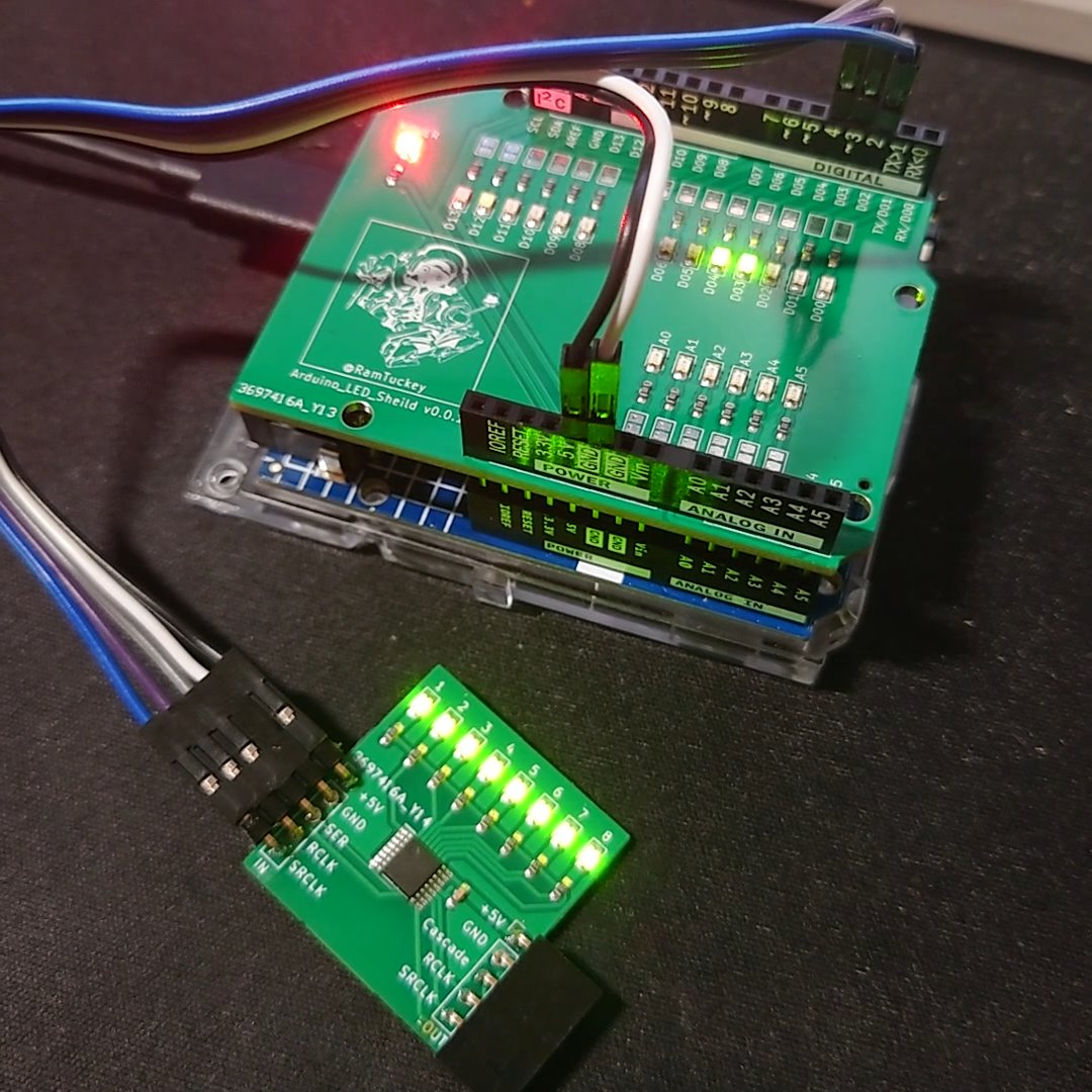
This project uses the same LED shield for Arduino UNO featured in the earlier cellular automaton demo.
Equipment
- Arduino UNO R4 Minima
- LED shield for Arduino UNO (LEDs on all 20 pins)
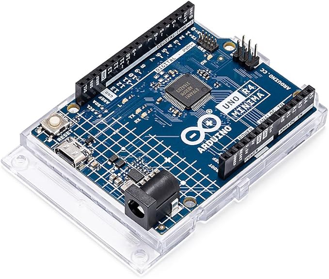
Arduino UNO R4 Minima
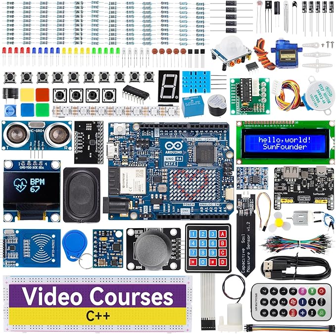
Arduino UNO R4 Minima starter kit
The R4’s processing speed is the key
The Arduino UNO R4 runs at a 48 MHz clock. That headroom is what allows every pin to be driven in software without dropping frames — the animation is smooth enough that no flicker shows up even on camera.
The Core Technique: What Is Software PWM?
How PWM works
Arduino provides a handful of pins capable of analog output via analogWrite(). These are hardware PWM (Pulse Width Modulation) pins, backed by a dedicated timer circuit.
PWM is simply switching a pin on and off extremely quickly.
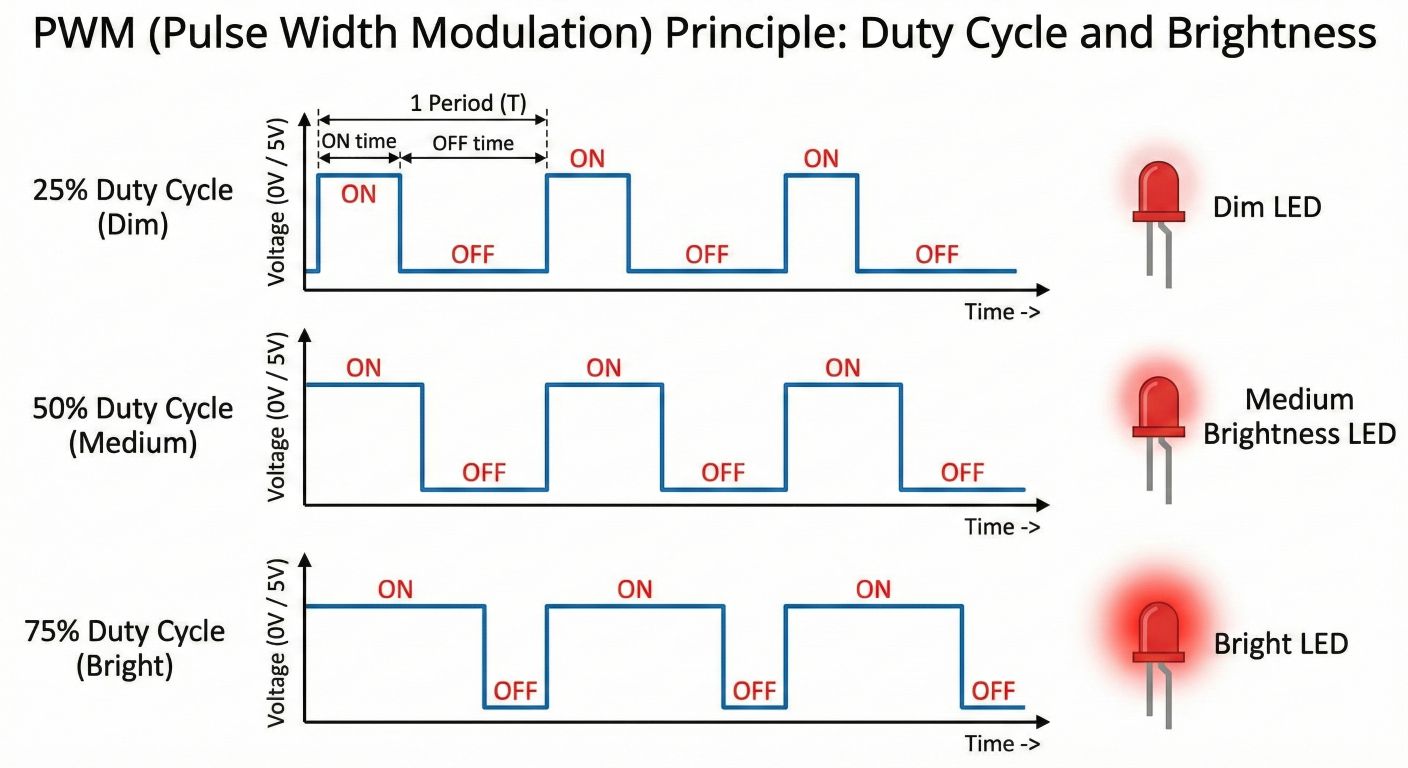
The PWM principle: brightness is set by how long the pin stays ON (the duty cycle)
A longer ON time (pulse width) looks brighter; a shorter one looks dimmer. The switching is far too fast for the human eye to resolve (typically 490 Hz–980 Hz), so we perceive a continuous change in brightness instead of flashing.
Duty cycle 25%: ■□□□■□□□■□□□  → dim
Duty cycle 50%: ■■□□■■□□■■□□  → medium
Duty cycle 75%: ■■■□■■■□■■■□  → bright
Why “Software”?
On a standard Arduino UNO (R3 or R4), only about six pins support hardware PWM. This LED shield, however, carries 20 LEDs (14 on D0–D13 plus 6 on A0–A5).
If you want brightness control on every pin, the hardware PWM pins simply are not enough.
The workaround is to brute-force the switching in software, and that technique is called Software PWM.
How Software PWM is implemented
// The basic idea (simplified)
void softwarePWM(int brightness) {  // brightness: 0-255
  for (int cycle = 0; cycle < 256; cycle++) {
    if (brightness > cycle) {
      digitalWrite(LED_PIN, HIGH);  // ON
    } else {
      digitalWrite(LED_PIN, LOW);   // OFF
    }
    delayMicroseconds(10);  // short wait
  }
}
A counter runs from 0 to 255. While the counter is below the target brightness the pin stays ON; once it passes, the pin goes OFF. Run this in parallel across every pin and you can control the brightness of all of them simultaneously.
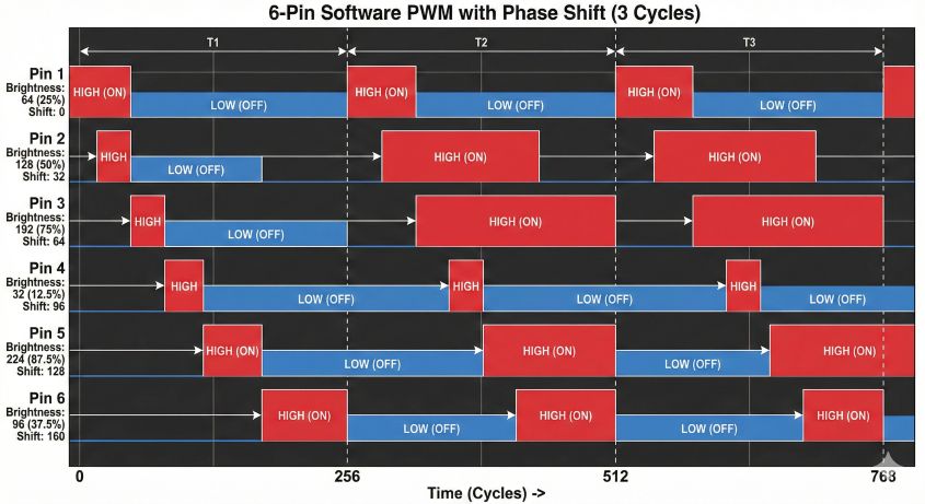
Software PWM timing chart
The Arduino UNO R4’s Processing Headroom
The UNO R4 (RA4M1, 48 MHz) makes all of the following possible:
- Raw speed: drives all 20 pins at high frequency while computing the wave math in parallel
- High-resolution timing:
micros()gives fine-grained control for a clean PWM waveform - Flicker-free: a PWM frequency in the kilohertz range is easy on both eyes and camera sensors
The result is smooth animation even with full-pin Software PWM and non-trivial wave calculations running together.
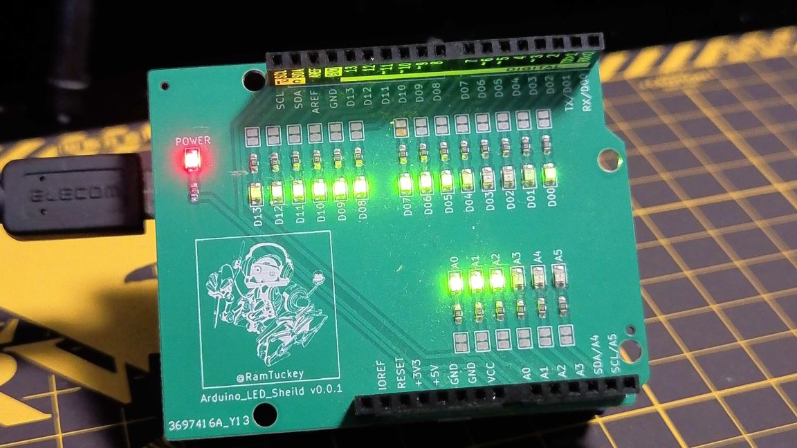
LEDs fading smoothly, with no visible flicker
Three “Waves of Light”
Three algorithms are implemented, and the sketch cycles between them roughly every 10 seconds.
1. Deep Ocean
Characteristics
- Motion: a large wave drifting slowly from left to right
- Period: about 3 seconds per cycle (a slow, breathing rhythm)
- Technique: gamma correction (γ = 2.0) applied
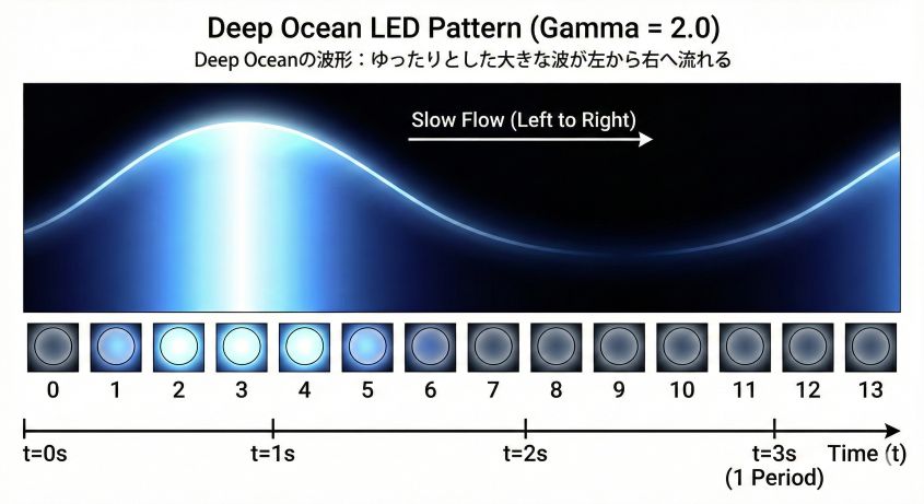
The Deep Ocean waveform: a long, slow wave travelling left to right
What is gamma correction?
The human eye perceives brightness logarithmically. We are very sensitive to small changes in dark regions, and much less sensitive in bright ones.
With a plain sin() function, the dark end of the range collapses into solid black and all of that gradation is lost.
Squaring the computed brightness value (γ = 2.0) restores detail in the shadows and produces a change in brightness that looks natural to the eye.
// Gamma correction
float linearBrightness = (sin(t) + 1.0) * 127.5;  // 0-255
float correctedBrightness = pow(linearBrightness / 255.0, 2.0) * 255.0;
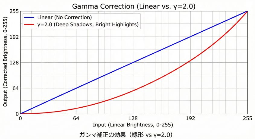
The effect of gamma correction (linear vs. γ = 2.0)
Why it’s worth watching
This is the calm, meditative mode. The gradation in the dark regions is remarkably rich — it feels like watching light shift through deep water.
2. Cyber Pulse
Characteristics
- Motion: tight ripples racing in reverse (right to left)
- Period: about 1 second per cycle (a sharp, pulsing feel)
- Wavelength: three times finer than Deep Ocean (
waveLen = 0.6)
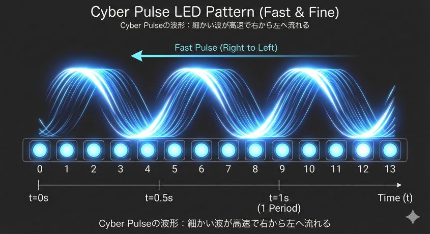
The Cyber Pulse waveform: fine ripples moving quickly from right to left
The technical trick
Reversing the direction of travel only requires flipping the sign on the position term.
// Deep Ocean (left to right)
float val = sin(t * speed + i * waveLen);

// Cyber Pulse (right to left)
float val = sin(t * speed - i * waveLen);  // sign inverted
Why it’s worth watching
It looks like data streaming across a bus — a distinctly cyberpunk effect that makes the R4’s speed visible. Think of the computer displays in a science fiction film.
3. Sonar Ripple
Characteristics
- Motion: ripples spreading from the centre of the board outward
- Period: about 2 seconds per cycle
- Spatial feel: a two-dimensional ripple rendered on a one-dimensional row of LEDs
The algorithm
The distance from the centre (between D6 and D7, i.e. index 6.5) is computed and folded into the phase.
for (int i = 0; i < 14; i++) {
  float dist = abs(i - 6.5);  // distance from centre
  float val = sin(t * speed - dist * waveLen);
  // ...
}
The wave is born at the centre and propagates outward, producing a ripple effect.
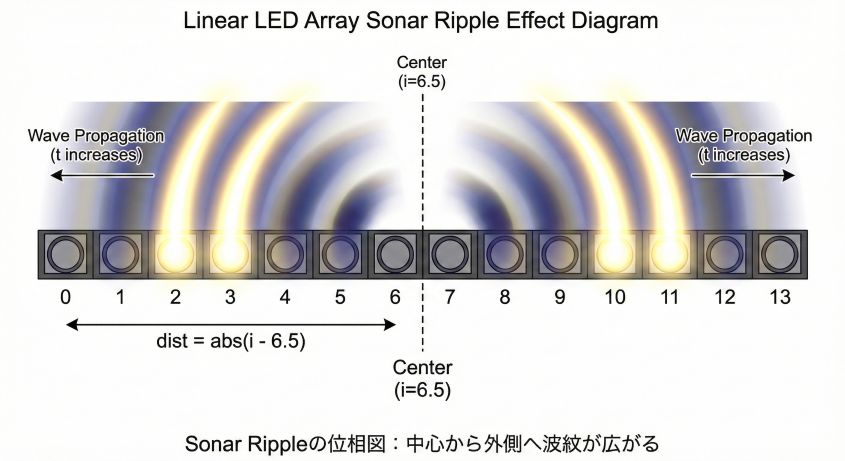
Sonar Ripple phase diagram: ripples expanding from the centre outward
Why it’s worth watching
It evokes sonar or ripples on water — a real sense of physical propagation. Despite the LEDs sitting in a single line, the effect reads as spatial depth.
Bonus: the linked level meter
The six pins on the bottom row (A0–A5) are not just decoration.
They compute the average brightness of the D0–D13 wave above and display it as a 6-bit bar graph.
// Compute the energy of the wave above
int avgBrightness = 0;
for (int i = 0; i < 14; i++) {
  avgBrightness += waveBrightness[i];
}
avgBrightness /= 14;  // average

// Convert to a 6-bit bar graph (0-6 LEDs lit)
int barLevel = map(avgBrightness, 0, 255, 0, 6);
for (int i = 0; i < 6; i++) {
  levelMeterState[i] = (i < barLevel) ? 1 : 0;
}
The board now looks like it is measuring the energy of the wave, which adds a satisfying instrument-like precision to the whole thing.
Complete Source Code
Here is the full Arduino sketch as it actually runs.
/*
  Demo: 3-Pattern PWM Wave Animation
  Board: Arduino Uno R4 Minima / WiFi

  D0-D13: Wave Display (14 LEDs)
  A0-A5 : Level Meter (6 LEDs)
*/

// Pin definitions
const int wavePins[] = { 0, 1, 2, 3, 4, 5, 6, 7, 8, 9, 10, 11, 12, 13 };
const int numWavePins = sizeof(wavePins) / sizeof(wavePins[0]);
const int meterPins[] = { A0, A1, A2, A3, A4, A5 };
const int numMeterPins = sizeof(meterPins) / sizeof(meterPins[0]);

// Wave pattern definition
struct WavePattern {
  float speed;      // speed (wave period)
  float waveLen;    // wavelength (phase offset between adjacent LEDs)
  bool reverse;     // reverse-direction flag
  bool ripple;      // ripple-mode flag
  bool useGamma;    // gamma-correction flag
};

WavePattern patterns[] = {
  { 0.002,  0.2,  false, false, true  },  // Deep Ocean (with gamma correction)
  { 0.006,  0.6,  true,  false, false },  // Cyber Pulse (fast, reversed)
  { 0.003,  0.4,  false, true,  false }   // Sonar Ripple (ripple mode)
};
int currentPattern = 0;
unsigned long patternStartTime = 0;
const unsigned long patternDuration = 10000;  // switch every 10 seconds

// Brightness arrays
byte waveBrightness[14];
byte levelMeterState[6];

void setup() {
  // Initialise pins
  for (int i = 0; i < numWavePins; i++) {
    pinMode(wavePins[i], OUTPUT);
  }
  for (int i = 0; i < numMeterPins; i++) {
    pinMode(meterPins[i], OUTPUT);
  }

  patternStartTime = millis();
}

void loop() {
  unsigned long currentMillis = millis();

  // Check whether it is time to switch patterns
  if (currentMillis - patternStartTime > patternDuration) {
    currentPattern = (currentPattern + 1) % 3;
    patternStartTime = currentMillis;
  }

  WavePattern &p = patterns[currentPattern];

  // --- Phase 1: calculation ---
  // Use sin() to compute the target brightness (0-255) for each LED
  for (int i = 0; i < numWavePins; i++) {
    float phase;

    if (p.ripple) {
      // Ripple mode: phase is derived from the distance to the centre
      float dist = abs(i - 6.5);  // distance from the centre (6.5)
      phase = currentMillis * p.speed - dist * p.waveLen;
    } else {
      // Normal mode: a wave travelling left to right (or reversed)
      phase = currentMillis * p.speed + (p.reverse ? -1 : 1) * i * p.waveLen;
    }

    float val = sin(phase);
    float brightness = (val + 1.0) * 127.5;  // map -1..1 to 0..255

    // Gamma correction (Deep Ocean only)
    if (p.useGamma) {
      brightness = pow(brightness / 255.0, 2.0) * 255.0;
    }

    waveBrightness[i] = (byte)brightness;
  }

  // Level meter (average brightness of the wave)
  int avgBrightness = 0;
  for (int i = 0; i < numWavePins; i++) {
    avgBrightness += waveBrightness[i];
  }
  avgBrightness /= numWavePins;

  int barLevel = map(avgBrightness, 0, 255, 0, numMeterPins);
  for (int i = 0; i < numMeterPins; i++) {
    levelMeterState[i] = (i < barLevel) ? 1 : 0;
  }

  // --- Phase 2: rendering (Software PWM) ---
  // Spinning this loop quickly is what fakes an analog output
  unsigned long pwmStart = micros();
  while (micros() - pwmStart < 5000) {  // render for 5 ms (= 200 Hz refresh)
    int pwmCycle = micros() & 0xFF;  // 0-255 counter

    // PWM for the wave
    for (int i = 0; i < numWavePins; i++) {
      digitalWrite(wavePins[i], (waveBrightness[i] > pwmCycle) ? HIGH : LOW);
    }

    // PWM for the level meter
    for (int i = 0; i < numMeterPins; i++) {
      digitalWrite(meterPins[i], levelMeterState[i]);
    }
  }
}
Code Walkthrough
1. Patterns held in a struct
struct WavePattern {
  float speed;    // speed
  float waveLen;  // wavelength
  bool reverse;   // reverse direction
  bool ripple;    // ripple mode
  bool useGamma;  // gamma correction
};
Keeping the parameters for all three patterns in an array and switching on currentPattern avoids duplicating the rendering code three times.
2. Calculation and rendering are separated
// Phase 1: calculation (a few ms)
for (int i = 0; i < 14; i++) {
  waveBrightness[i] = calculate(...);
}

// Phase 2: rendering (tight loop for 5 ms)
while (micros() - pwmStart < 5000) {
  // toggle every pin as fast as possible
}
Splitting the expensive math (sin() and friends) from the cheap output (digitalWrite()) keeps the rendering phase tight.
3. Microsecond-resolution PWM
int pwmCycle = micros() & 0xFF;  // 0-255 counter
digitalWrite(pin, (brightness > pwmCycle) ? HIGH : LOW);
The low 8 bits of micros() (0–255) serve as the PWM counter, and each pin compares its target brightness against it.
One full pass through the counter takes about 256 µs (0.256 ms), giving a PWM frequency of roughly 3.9 kHz. That is well beyond what the eye can resolve, and high enough that cameras rarely pick up banding.
The R4’s 48 MHz clock is what makes this high-frequency PWM viable, producing brightness transitions that look natural to both eyes and camera sensors.
Summary: A Debug Tool Turned Art Gadget
This LED shield was originally built as a debugging tool — for blinking LEDs and checking pin states at a glance.
With nothing but a change of software, it also works as:
- a wave simulator
- a 1/f fluctuation ambient gadget
- an interior light
- a programming teaching aid
What this project demonstrates
- Being single-purpose hardware (just LEDs on pins) is the same thing as being able to become anything, given the right software
- The performance jump in the Arduino R4 is what promotes a brute-force technique like Software PWM to something genuinely practical
- Tuning for human perception — gamma correction above all — is what separates “it fades” from “it looks beautiful”
Ideas to take further
The sketch above is a good starting point for extensions such as:
- Audio reactive: pick up sound with a microphone and modulate the wave speed or amplitude
- Temperature linked: change the character of the wave based on room temperature
- Bluetooth control: switch patterns and tune parameters from a phone app
- Multi-board sync: line up several shields and propagate a single wave across all of them
Take the code and invent your own way to make light move.
Where to Get It
Available on BOOTH
Price: ¥2,000 (tax included, shipping extra)
Open source resources
The schematic and the Software PWM sketch shown here are published on GitHub:
Schematics, board data, and sample code are free to use
A digital pin that can only do on and off starts to breathe once software gets involved.
That is the moment the line between hardware and software stops being obvious.
Grab the shield and go write your own algorithm of light.
Related Articles
- Arduino LED Circuit for Beginners: Ohm’s Law Resistor Calculation: Start here if you are new to driving LEDs — the resistor math behind every circuit on this page.
- Arduino RGB LED PWM Control: 8 Colors to 16.7 Million: Hardware PWM applied to color mixing, including the same sine-wave phase technique used here.
- 74HC595 Shift Register: Drive Multiple LEDs from Arduino: The hardware answer to running out of pins, as opposed to the software one shown here.