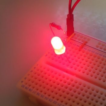
This article contains affiliate links (Amazon Associates).
Introduction: Why ADC Matters
Quick answers:
- How do you turn an analog sensor reading into a number? →
analogRead()returns an ADC value from 0 to 1023 - How do you convert that back to volts? →
voltage = ADC value × (5.0 / 1023.0) - How do you get the R4’s high-precision 14-bit mode? → just call
analogReadResolution(14)
Analog voltage signals — the output of a temperature sensor, the reading from a photocell, the tilt reported by an accelerometer — all need to become numbers before software can do anything with them. That conversion is ADC (analog-to-digital conversion).
The Arduino is a digital device and cannot interpret an analog signal directly. Its built-in ADC converts an analog voltage into an integer between 0 and 1023 so that your program can work with it.
In this article we’ll vary a voltage with a potentiometer, read it with the ADC, and visualise the result two ways at once: as LED brightness (PWM output) and as text over serial. It’s a step beyond blinking an LED — you get to see the full analog → digital → control loop that every sensor project is built on.
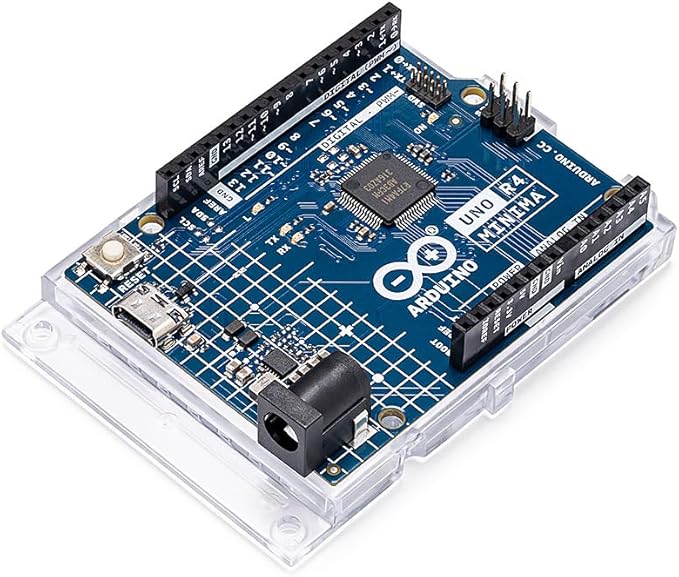
Arduino UNO R4 Minima

Arduino UNO R4 Minima starter kit
About the Arduino UNO R4
The UNO R4 used here replaces the R3’s AVR with a Renesas 32-bit ARM Cortex-M4 (RA4M1), which is a substantial jump in processing power. The pinout and the basic ADC behaviour remain fully compatible with the R3, so everything in this article also runs unchanged on an R3.
Key specifications
- MCU: Renesas RA4M1 (Cortex-M4, 48 MHz)
- Operating voltage: 5 V
- ADC resolution: up to 14-bit (enable with
analogReadResolution(14); defaults to 10-bit for compatibility) - Analog input pins: A0–A5 (6 channels)
- PWM output pins: D3, D5, D6, D9, D10, D11 (6 pins)
ADC resolution: R3 vs. R4
| UNO R3 (ATmega328P) | UNO R4 (RA4M1) | |
|---|---|---|
| Default resolution | 10-bit (0–1023) | 10-bit (0–1023) |
| Maximum resolution | 10-bit | 14-bit (0–16383) |
| Reference voltage | 5 V | 5 V |
| Volts per step (default) | 4.88 mV | 4.88 mV |
| Volts per step (14-bit) | — | 0.305 mV |
| MsTimer2 support | ✅ Supported | ❌ Not supported (use millis()) |
Out of the box the R4 behaves exactly like the R3, but adding a single call to analogReadResolution(14) increases the resolution by roughly 16×.
ADC Fundamentals
What resolution means, and how to convert to volts
The Arduino UNO’s ADC has 10-bit resolution. That means it divides the reference voltage (5 V by default) into 1024 steps (0–1023).
Working out the step size:
Voltage step = 5V ÷ 1024 = 0.00488V ≈ 4.88mV
So the ADC resolves voltage in steps of about 4.88 mV. For example, an ADC reading of 512 corresponds to:
Voltage = 512 × (5V / 1024) = 2.5V
How the conversion works inside: the SAR ADC
The Arduino’s ADC is a SAR (Successive Approximation Register) converter. It narrows in on the input voltage by repeatedly halving the range — exactly like a binary search.
The conversion process
At 10-bit resolution it takes 10 comparisons to settle on a value. Here is what happens with a 3.2 V input:
Step 1: determine the most significant bit (MSB)
Comparison voltage = 5V ÷ 2 = 2.5V
Input (3.2V) > 2.5V → bit 9 = 1
Narrow the range to 2.5V-5V
Step 2: determine the next bit
Comparison voltage = 2.5V + (5V - 2.5V) ÷ 2 = 3.75V
Input (3.2V) < 3.75V → bit 8 = 0
Narrow the range to 2.5V-3.75V
Step 3: keep narrowing
Comparison voltage = 2.5V + (3.75V - 2.5V) ÷ 2 = 3.125V
Input (3.2V) > 3.125V → bit 7 = 1
Narrow the range to 3.125V-3.75V
Repeat ten times and you arrive at a final integer between 0 and 1023.
The hardware behind it
A SAR ADC consists of four main blocks:
-
Comparator
- Compares the input voltage against the current reference voltage
- Outputs a single bit: HIGH (1) or LOW (0)
-
DAC (digital-to-analog converter)
- Turns the internally generated digital value into the analog comparison voltage
- Produces the reference for each step
-
SAR (successive approximation register)
- Stores each comparison result and computes the next comparison voltage
- Resolves 10 bits one at a time
-
Sample-and-hold circuit
- Captures the input voltage at the start of the conversion
- Keeps the measurement accurate even if the input moves mid-conversion
Trading speed against accuracy
The ADC in the Arduino UNO (ATmega328P) runs from a divided-down system clock (16 MHz).
ADC clock frequency:
ADC clock = 16MHz ÷ 128 (prescaler) = 125kHz
Time for one conversion:
Conversion time = 13 clock cycles ÷ 125kHz ≈ 104μs
Those 13 cycles break down as:
- Sampling: 1.5 cycles
- Conversion (10 comparisons): 10 cycles
- Overhead: 1.5 cycles
A note on going faster: A smaller prescaler speeds things up, but accuracy degrades once the ADC clock exceeds 200 kHz. The Arduino default (divide by 128) is chosen to balance speed against accuracy.
The binary search analogy
It is the same idea as binary search in software:
// Binary search, in pseudocode
int low = 0, high = 1023;
while (low < high) {
  int mid = (low + high) / 2;
  if (input voltage > the voltage corresponding to mid) {
    low = mid + 1;  // search the upper half
  } else {
    high = mid;     // search the lower half
  }
}
return low;  // the final ADC value
A SAR ADC is that search executed at high speed in analog hardware.
ADC value to voltage
| ADC value | Voltage (V) | Percentage |
|---|---|---|
| 0 | 0.00 | 0% |
| 256 | 1.25 | 25% |
| 512 | 2.50 | 50% |
| 768 | 3.75 | 75% |
| 1023 | 5.00 | 100% |
About AREF (the reference voltage)
The Arduino has an AREF pin. Feeding an external voltage into it changes the ADC’s reference. Referencing 3.3 V, for instance, gives finer resolution over a lower voltage range.
⚠️ Warning: you must call
analogReference(EXTERNAL)in your sketch before applying a voltage to AREF. Driving AREF without that setting can damage the microcontroller.
The ADC in the Arduino UNO R4 Minima supports up to 14 bits (0–16383) in hardware. Enabling it takes one call to analogReadResolution(14) in setup().
analogReadResolution(14);                       // switch to 14-bit mode
int adcValue = analogRead(A0);                 // now returns 0-16383
float voltage = adcValue * 5.0 / 16383.0;     // convert to volts
The resolution becomes 5V ÷ 16384 ≈ 0.305 mV, roughly 16× finer than 10-bit. It’s worth using whenever you need precise voltage measurement. If you want to stay compatible with the R3, leave it at the default 10-bit.
What We’re Building
The experiment implements four things:
- A potentiometer to sweep a voltage across the 0–5 V range
- ADC conversion (pin A0) to read that voltage
- PWM output (pin D9) to set LED brightness
- Serial output sending the voltage to the PC every 100 ms
Together these give you the fundamental flow of every sensor project: analog input → digital processing → analog output (PWM).
Circuit Design
Parts
| Part | Spec | Qty |
|---|---|---|
| Arduino UNO R4 (or R3) | 5 V operation | 1 |
| Potentiometer | 10 kΩ | 1 |
| LED | Red (Vf = 1.8–2.2 V) | 1 |
| Carbon resistor | 220 Ω (current limiting) | 1 |
| Breadboard | Standard size | 1 |
| Jumper wires | As needed | - |
Schematic
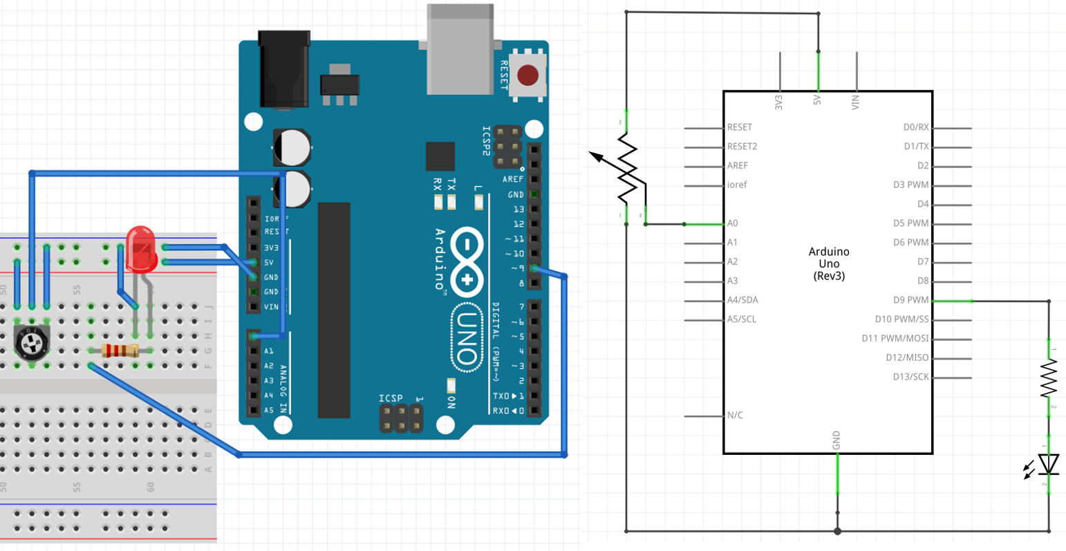
Schematic for the ADC and PWM circuit
Wiring notes
The potentiometer
A potentiometer has three terminals — two ends and a wiper:
- Terminal 1: 5 V (Arduino VCC)
- Terminal 2: pin A0 (Arduino)
- Terminal 3: GND (Arduino GND)
Turning the knob sweeps the wiper voltage continuously between 0 V and 5 V.
The LED
- Pin D9 (PWM output) → 220 Ω resistor → LED anode (+) → LED cathode (−) → GND
Choosing the 220 Ω current-limiting resistor:
With a forward voltage of Vf = 2.0 V and a target current of 20 mA:
R = (5V - 2.0V) / 0.02A = 150Ω
Using 220 Ω instead limits the current to about 13.6 mA, which extends the life of the LED.
The Code
This sketch converts the ADC reading to a voltage, drives the LED with PWM, and reports over serial.
#include <MsTimer2.h>  // timer interrupt library

const int LED_PIN = 9;    // PWM output pin
int adcValue = 0;         // ADC reading (0-1023)
float voltage = 0.0;      // voltage (V)

// Timer interrupt handler (runs every 100 ms)
void timerInterrupt() {
  voltage = adcValue * 5.0 / 1023.0;  // convert the ADC reading to volts
  Serial.print("ADC: ");
  Serial.print(adcValue);
  Serial.print(" | Voltage: ");
  Serial.print(voltage, 3);  // print to 3 decimal places
  Serial.println(" V");
}

void setup() {
  pinMode(LED_PIN, OUTPUT);

  Serial.begin(9600);
  while (!Serial) {
    ; // wait for the serial port (needed on the R4 Minima)
  }

  // Configure the timer interrupt (100 ms interval)
  MsTimer2::set(100, timerInterrupt);
  MsTimer2::start();

  Serial.println("AD Conversion Started");
  Serial.println("ADC | Voltage (V)");
  Serial.println("----+-------------");
}

void loop() {
  // Read the analog value on A0 (0-1023)
  adcValue = analogRead(A0);

  // Scale the ADC reading to a PWM value (0-255)
  int pwmValue = adcValue / 4;  // 1023 ÷ 4 ≈ 255

  // Set the LED brightness via PWM
  analogWrite(LED_PIN, pwmValue);

  delay(10);  // short delay for stability
}
How the program works
1. Performing the conversion (in loop())
adcValue = analogRead(A0);
analogRead() measures the voltage on the given analog pin (A0–A5) and returns an integer between 0 and 1023.
The conversion takes roughly 100 µs.
2. Scaling to a PWM value
int pwmValue = adcValue / 4;
This maps the ADC range (0–1023) onto the PWM range (0–255). analogWrite() only accepts 0–255, so dividing by four lines the ranges up.
- ADC = 0 → PWM = 0 (off)
- ADC = 512 → PWM = 128 (about half brightness)
- ADC = 1023 → PWM = 255 (full brightness)
3. Driving the PWM output
analogWrite(LED_PIN, pwmValue);
analogWrite() emits a PWM (pulse width modulation) signal. On the Arduino UNO R4 the frequency is about 490 Hz, and the duty cycle runs from 0 to 100 % (specified as 0–255).
Duty cycle examples:
- 0: always LOW (0 V) → LED off
- 128: HIGH half the time (equivalent to 2.5 V) → LED at half brightness
- 255: always HIGH (5 V) → LED at full brightness
4. Sending data on a fixed schedule with a timer interrupt
MsTimer2::set(100, timerInterrupt);
The MsTimer2 library calls timerInterrupt() every 100 ms.
Why bother with an interrupt?
- Doing serial I/O inside
loop()makes the loop rate vary - An unstable transmission interval makes the data hard to analyse quantitatively
- An interrupt gives you an exact, repeatable interval
This matters a great deal for sensor logging and any kind of instrumentation work.
Installing the MsTimer2 Library
MsTimer2 writes directly to the Timer2 hardware registers of the ATmega (AVR). It cannot be used on the Arduino UNO R4 Minima or R4 WiFi, which are built around the RA4M1 (ARM Cortex-M4).
- Arduino UNO R3 / Mega / Nano (AVR family) → MsTimer2 works
- Arduino UNO R4 Minima / R4 WiFi (RA4M1) → use the
millis()alternative shown below
To use MsTimer2.h you need to install the library from the Arduino IDE.
Installation (AVR boards such as R3 and Mega only)
- Open the Arduino IDE
- From the menu bar choose Sketch → Include Library → Manage Libraries…
- In the Library Manager, search for “MsTimer2”
- Select “MsTimer2 by Javier Valencia” and click Install
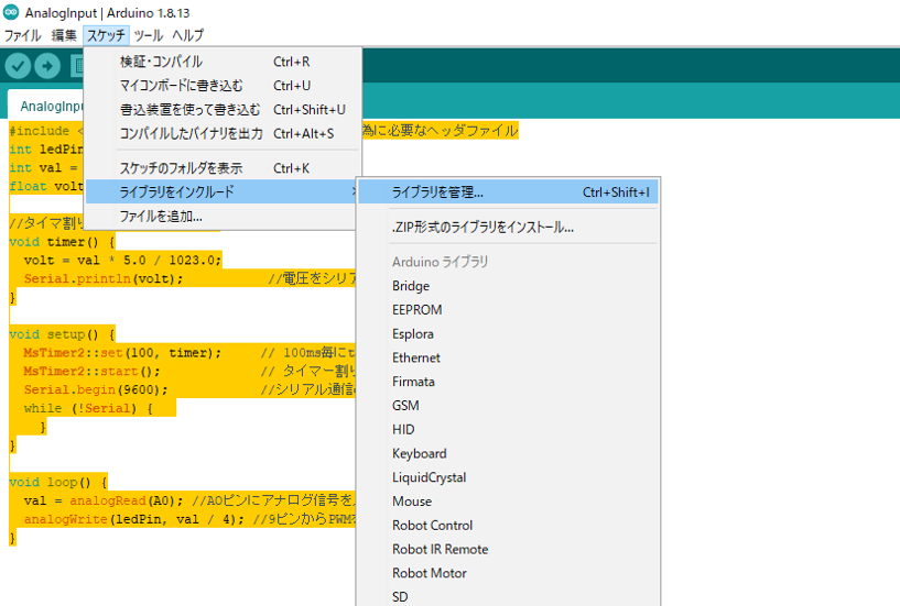
Opening the Library Manager
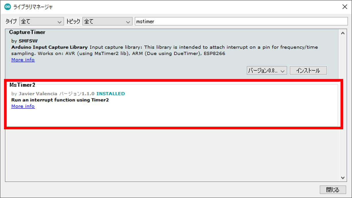
Searching for and installing the MsTimer2 library
Once installed, #include <MsTimer2.h> becomes available.
Notes for the Arduino UNO R4
The Timer2 implementation the R3 relied on differs on the R4. If MsTimer2 does not work, use one of these alternatives:
Alternative 1: a timer built on millis() (works on R3 and R4 — recommended)
unsigned long previousMillis = 0;
const long interval = 100;  // 100 ms

void loop() {
  unsigned long currentMillis = millis();

  if (currentMillis - previousMillis >= interval) {
    previousMillis = currentMillis;
    // put the once-per-100ms work here
    voltage = adcValue * 5.0 / 1023.0;
    Serial.println(voltage);
  }

  adcValue = analogRead(A0);
  analogWrite(LED_PIN, adcValue / 4);
}
Alternative 2: the FspTimer library (R4 only, advanced)
On the R4 series, the FspTimer library from the Renesas FSP (Flexible Software Package) gives direct control over the hardware timer interrupts. Configuration is considerably more involved, and alternative 1 is sufficient for most use cases.
Checking the Serial Output
After uploading, open the serial monitor to confirm everything works.
Opening the serial monitor
- Click the magnifying glass icon (Serial Monitor) at the top right of the Arduino IDE
- Set the baud rate at the bottom right to 9600 baud
- Turn the potentiometer and watch the voltage update in real time
Example output:
AD Conversion Started
ADC | Voltage (V)
----+-------------
ADC: 0 | Voltage: 0.000 V
ADC: 256 | Voltage: 1.252 V
ADC: 512 | Voltage: 2.504 V
ADC: 768 | Voltage: 3.757 V
ADC: 1023 | Voltage: 5.009 V
Verification and Accuracy
Watching it run
Here is the circuit in operation:
What to watch for:
- Red trace: the analog voltage coming out of the potentiometer
- Yellow trace: the PWM signal going into the LED
As the voltage changes, the PWM pulse width (duty cycle) tracks it proportionally and the LED brightness follows smoothly.
Measurement accuracy
Comparing a multimeter reading against the value the Arduino computes:
| Multimeter | ADC value | Arduino’s figure | Error |
|---|---|---|---|
| 1.25V | 256 | 1.252V | +0.002V |
| 2.50V | 512 | 2.504V | +0.004V |
| 3.75V | 768 | 3.757V | +0.007V |
Everything lands within about 0.01 V, which is plenty for general hobby electronics.
PWM frequency
Measured on an oscilloscope, the PWM frequency on the Arduino UNO R4 is about 490 Hz. That’s fast enough that the eye reads it as a smooth change in brightness rather than flicker.
Extending This to Real Sensors
A few directions this circuit and sketch lead to.
1. A temperature sensor (LM35)
The LM35 outputs a voltage proportional to temperature (10 mV/°C).
voltage = adcValue * 5.0 / 1023.0;
temperature = voltage * 100.0;  // convert to degrees Celsius
Serial.print("Temperature: ");
Serial.print(temperature);
Serial.println(" °C");
2. A light sensor (CdS photocell)
A CdS cell changes resistance with light level, which gives you an auto-dimming LED.
int brightness = map(adcValue, 0, 1023, 255, 0);  // brighter room = dimmer LED
analogWrite(LED_PIN, brightness);
3. Battery voltage monitoring
With a voltage divider you can monitor a lithium-ion cell (3.7–4.2 V).
float batteryVoltage = voltage * 2.0;  // divider ratio
if (batteryVoltage < 3.3) {
  Serial.println("Battery Low!");
}
Troubleshooting
Problem 1: the voltage reading is noisy
Cause: a floating analog input, or a loose connection
Fix:
- Add a pull-up or pull-down resistor
- Average several readings
int sum = 0;
for (int i = 0; i < 10; i++) {
  sum += analogRead(A0);
  delay(1);
}
adcValue = sum / 10;  // average of 10 samples
Problem 2: the LED flickers under PWM
Cause: the PWM frequency is too low, or the supply voltage is unstable
Fix:
- Use a regulated supply
- Add a capacitor (100 µF) between VCC and GND
Problem 3: the serial output is garbled
Cause: mismatched baud rates
Fix:
- Set both the sketch and the serial monitor to 9600
- On the Arduino UNO R4, wait for initialisation with
while (!Serial) {}
Summary
Using the Arduino’s ADC, this project covered:
✅ Voltage measurement with a 10-bit ADC (4.88 mV resolution) ✅ LED dimming via PWM (256 levels) ✅ Periodic data transmission using a timer interrupt (100 ms interval) ✅ Visualising the result over serial
These techniques underpin every analog sensor you’ll ever use — temperature, light, pressure, and the rest. The flow of “digitise an analog signal, process it, produce an output” is the heart of IoT devices and robot control alike.
As a next step, look into I2C digital sensors, or higher-precision 16-bit ADCs such as the ADS1115.
Related Articles
- Arduino LED Circuit for Beginners: Ohm’s Law Resistor Calculation: The resistor math behind the LED used in this circuit.
- Arduino RGB LED PWM Control: 8 Colors to 16.7 Million: A deeper look at the
analogWrite()PWM output used here. - Arduino Electronic Piano: Play Music with a Piezo Buzzer: Digital input with internal pull-ups, the counterpart to the analog input covered here.
- 74HC595 Shift Register: Drive Multiple LEDs from Arduino: What to do once you run out of pins.
See you…