This article contains affiliate links (Amazon Associates).
Introduction: The Joy of Making Music with Arduino
Ever wanted to build a musical instrument out of electronics?
In this project we’ll build a genuinely playable electronic piano using an Arduino UNO R4 and a piezo buzzer. You control the pitch in software, and the whole thing comes together in about an hour.
We’ll walk through how the sound is produced, how to design the circuit, and how the code works — all at a pace that assumes no prior experience. At the end, there’s a video of the Arduino playing a melody entirely on its own.
📝 What you’ll learn:
- How a piezo buzzer actually produces sound
- How to generate musical notes with the
tone()function - Circuit design and wiring for an electronic piano
- The programming techniques needed to play a real tune
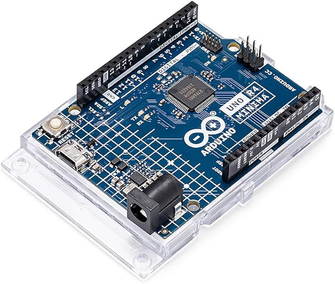
Arduino UNO R4 Minima
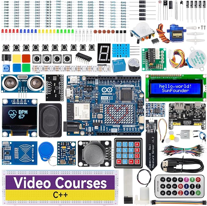
Arduino UNO R4 Minima starter kit
🎵 Parts List
Required parts
| Part | Qty | Purpose | Approx. price |
|---|---|---|---|
| Arduino UNO R4 Minima/WiFi | 1 | Main controller board | ¥3,000–4,000 |
| Piezo buzzer (passive type) | 1 | The speaker that makes the sound | ¥50–100 |
| Tactile switches | 8 | Used as piano keys | ~¥10 each |
| Breadboard | 1 | Prototyping board | ~¥300 |
| Jumper wires (male-male) | ~20 | Wiring | ~¥500 (set) |
Optional parts (visual feedback)
| Part | Qty | Purpose | Approx. price |
|---|---|---|---|
| LEDs (red, green, etc.) | 8 | Light up the key being pressed | ~¥10 each |
| 330 Ω carbon resistors | 8 | Current limiting for the LEDs | ~¥5 each |
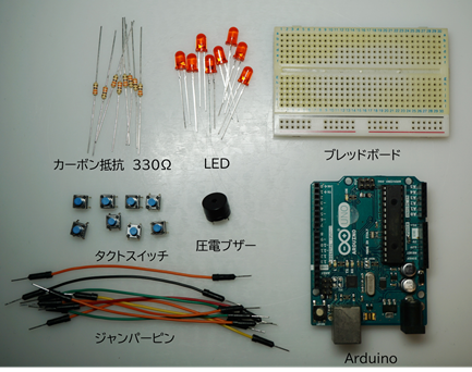
All the parts needed to build the electronic piano
💡 Starter kits are worth considering
If you’re starting from nothing, a kit bundling the Arduino UNO R4 with the common passive components usually works out cheaper than buying each part separately.
Arduino UNO R4 Minima
Arduino UNO R4 starter kit
ℹ️ Important Piezo buzzers come in active and passive varieties. This project needs the passive type. An active buzzer contains its own oscillator and can only produce one fixed tone, so it cannot play a scale. Look for packaging that says “Passive Buzzer” or “piezo speaker”.
🔧 How a Piezo Buzzer Works
The piezoelectric effect
A piezo buzzer produces sound using a physical phenomenon called the piezoelectric effect. A special ceramic material physically expands and contracts when a voltage is applied across it.
How that becomes sound:
- Voltage ON → the ceramic expands → it pushes the metal diaphragm → click
- Voltage OFF → the ceramic contracts → it pulls the diaphragm back → click
- Repeat that very quickly (say, 440 times per second) → we hear a continuous tone (the note A)
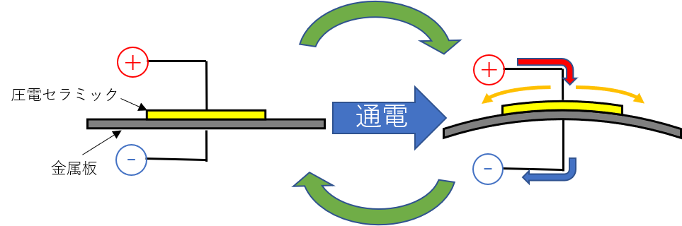
How a piezo buzzer works: switching the voltage vibrates the metal diaphragm, which moves air and produces sound
Pitch and frequency
The pitch of a note is set by how fast the vibration is — its frequency. Higher frequency means a higher note, lower frequency a lower one.
For example:
- C4: 523.3 Hz (523.3 vibrations per second)
- A4: 880 Hz (880 vibrations per second)
So all the Arduino has to do is output a pulse train at the frequency of the note you want, and the buzzer plays it.
📐 Circuit Design and Wiring
Overall schematic
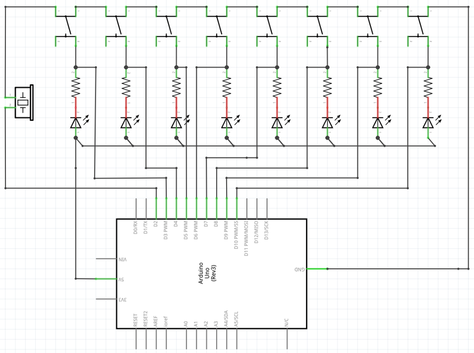
Electronic piano schematic: eight tactile switches select the note
What connects where:
| Pin | Part | Role |
|---|---|---|
| D2 | Piezo buzzer | The pin tone() drives |
| D3–D10 | Tactile switches (8) | Note inputs (using internal pull-ups) |
| D3–D10 | LED + 330 Ω resistor (8 each) | Visual feedback for the key pressed (optional) |
| 5V / GND | Power rails | Supplied from the Arduino |
Wiring notes
-
Piezo buzzer
- Positive (red) → pin D2
- Negative (black) → GND
-
Tactile switches
- One terminal → pins D3–D10 (one switch per pin)
- Other terminal → GND (shared)
- No external pull-up resistors needed, since we enable the internal ones in software
-
LEDs (optional)
- Anode (long leg) → each pin (D3–D10) through a 330 Ω resistor
- Cathode (short leg) → GND (shared)
💡 Working out the LED resistor value The resistor calculation is covered in detail here: 👉 Arduino LED Circuit for Beginners: Ohm’s Law Resistor Calculation
Breadboard layout
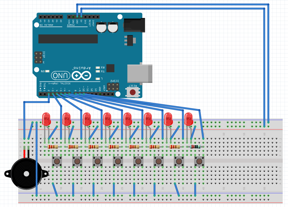
Breadboard wiring: colour-coded jumper wires keep it readable
Wiring tips:
- Sticking to a colour convention makes troubleshooting far easier later:
- Red: 5V
- Black: GND
- Blue: digital input
- Yellow: digital output
- Pick the simplest routing you can and avoid crossing wires
💻 The Code
Complete source
// Arduino electronic piano
// Play 8 notes through a piezo buzzer

void setup()
{
    // Set D3-D10 as inputs with the internal pull-up enabled
    for(int i=3; i<=10; i++) {
        pinMode(i, INPUT_PULLUP); // internal pull-up on (works on both R3 and R4)
    }

    // D2 drives the piezo buzzer (tone() configures it, so no pinMode needed)
}

void loop()
{
    int frequency = 0; // holds the frequency to output

    // Check each switch and set the matching frequency
    if(digitalRead(3)==LOW)  frequency = 523;  // C4
    if(digitalRead(4)==LOW)  frequency = 587;  // D4
    if(digitalRead(5)==LOW)  frequency = 659;  // E4
    if(digitalRead(6)==LOW)  frequency = 698;  // F4
    if(digitalRead(7)==LOW)  frequency = 784;  // G4
    if(digitalRead(8)==LOW)  frequency = 880;  // A4
    if(digitalRead(9)==LOW)  frequency = 988;  // B4
    if(digitalRead(10)==LOW) frequency = 1046; // C5 (high C)

    // Play if a frequency was selected, otherwise stay silent
    if (frequency != 0) {
        tone(2, frequency);  // output the pulse train on D2
    } else {
        noTone(2);           // stop the sound
    }
}
Walking through the code
setup(): initialisation
for(int i=3; i<=10; i++) {
    pinMode(i, INPUT_PULLUP); // internal pull-up on (works on both R3 and R4)
}
What this does:
- Configures D3–D10 as inputs with the internal pull-up resistor enabled
- With
INPUT_PULLUP, the internal pull-up is switched on:- Switch not pressed: HIGH (5 V)
- Switch pressed: LOW (0 V)
- No external pull-up resistors required
Older Arduino code sometimes used pinMode(i, INPUT) followed by digitalWrite(i, HIGH) to achieve the same thing, but that idiom does not always behave correctly on the R4 (Renesas RA4M1). Specifying INPUT_PULLUP directly is the correct modern approach.
loop(): the main routine
Step 1: read the switches
if(digitalRead(3)==LOW) frequency = 523;
digitalRead(3)reads the state of pin D3- If it reads LOW (the switch is pressed), set the frequency to 523 Hz
Step 2: output the note
if (frequency != 0) {
    tone(2, frequency);
} else {
    noTone(2);
}
tone(pin, frequency)outputs a pulse train at the given frequency- If no switch is pressed (
frequency == 0),noTone()silences the pin
How tone() works
tone(pin, frequency) is a built-in Arduino function.
What it does:
- Outputs a square wave (pulse train) at the specified frequency on the specified pin
- Uses a timer interrupt internally to generate an accurate frequency
- Cannot drive multiple pins at once (only one pin at a time on the Arduino UNO/R4)
Examples:
tone(2, 440);      // output 440 Hz (the note A) on D2
tone(2, 880, 500); // output 880 Hz for 500 ms (third argument = duration)
noTone(2);         // stop
🔗 Further reading Official Arduino reference for
tone(): https://www.arduino.cc/reference/en/language/functions/advanced-io/tone/
Frequently asked questions
Q: Why eight separate if statements? Wouldn’t a switch be better?
A: A switch works fine too. The if chain does have one useful property: if several switches are pressed at once, the last one checked wins. For more advanced behaviour (chords, for example), an array-driven approach is a better fit.
Q: I get no sound at all. What should I check?
A: Work through this list:
- Is the buzzer’s polarity (+/−) correct?
- Is it actually a passive buzzer? (An active one cannot change pitch.)
- Are the tactile switches wired correctly?
- Add
Serial.println(digitalRead(3));and watch the serial monitor to confirm the switches are being read
Q: How do I tell an active buzzer from a passive one?
A: The most reliable test is to connect it straight to a 3 V supply. If it emits a steady tone as soon as power is applied, it’s active. If it stays silent (or gives a single click), it’s passive. Packaging usually says “Passive Buzzer” or “piezo speaker”. You need the passive type to play different notes.
Q: Does tone() work on the Arduino UNO R4 (Minima / WiFi)?
A: Yes. The R4 uses a Renesas RA4M1 rather than an AVR, so the internal timer allocation differs, which can occasionally conflict with other libraries (Servo, analogWrite()). Be careful when using them together. The code in this article was verified on a UNO R4 Minima.
Q: Does using tone() disable PWM (analogWrite()) on other pins?
A: On the Arduino UNO (R3/R4), tone() claims one internal timer. On the UNO R3 it uses Timer2, which can affect the accuracy of analogWrite() on the pins tied to that timer (D3 and D11). Watch out for the conflict if you need PWM while a tone is playing. After calling noTone(), everything returns to normal.
Q: Can the Arduino play chords (several notes at once)?
A: The standard tone() function handles one pin and one note. To play chords, connect several piezo buzzers to different pins and call tone() on each — though the UNO has a limited number of timers. Alternatively, libraries such as TimerFreeTone synthesise chords in software.
Q: The sound cuts in and out. How do I make it stable?
A: Check the following:
- Loose jumper wires: if a wire is not fully seated in the breadboard, the connection drops intermittently. Push them all the way in.
- Buzzer wiring: confirm positive (red) goes to D2 and negative (black) goes to GND.
- Power quality: a poor USB supply can cause instability. Plug directly into the PC rather than through a hub.
- Loop speed: a fast
loop()can re-triggertone()repeatedly. If you want a note of a definite length, use the third argument —tone(pin, freq, duration)— for more stable playback.
🎼 Note-to-Frequency Table
Each musical note corresponds to a fixed frequency. Below are three octaves centred on middle C (C4).
Frequencies of the main notes
| Note | Octave 3 (lower) |
Octave 4 (middle C) |
Octave 5 (higher) |
Notation |
|---|---|---|---|---|
| Do | 261.6 Hz | 523.3 Hz | 1046.5 Hz | C3 / C4 / C5 |
| Re | 293.7 Hz | 587.3 Hz | 1174.7 Hz | D3 / D4 / D5 |
| Mi | 329.6 Hz | 659.3 Hz | 1318.5 Hz | E3 / E4 / E5 |
| Fa | 349.2 Hz | 698.5 Hz | 1396.9 Hz | F3 / F4 / F5 |
| Sol | 392.0 Hz | 784.0 Hz | 1568.0 Hz | G3 / G4 / G5 |
| La | 440.0 Hz | 880.0 Hz | 1760.6 Hz | A3 / A4 / A5 |
| Si | 493.9 Hz | 987.8 Hz | 1975.5 Hz | B3 / B4 / B5 |
📝 Good to know
- A4 = 440 Hz is the international concert pitch reference (ISO 16)
- Going up one octave doubles the frequency (A4 = 440 Hz → A5 = 880 Hz)
- The program in this article uses the octave 4 notes shown in bold
Using the table in code
Pick whatever frequencies you like from the table and drop them into the sketch:
// To use the lower register (octave 3)
if(digitalRead(3)==LOW) frequency = 262;  // low C (C3)

// To use the upper register (octave 5)
if(digitalRead(3)==LOW) frequency = 1047; // high C (C5)
🧪 Build It and Play It
The finished circuit
Here is the circuit assembled on a breadboard, following the schematic above.
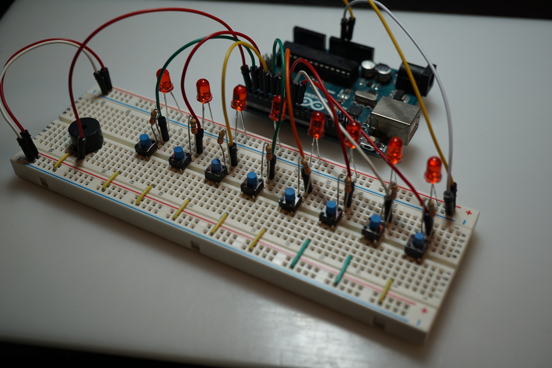
The finished electronic piano: eight tactile switches and a piezo buzzer
Assembly notes:
- It looks like a lot of wires, but it’s the same pattern repeated eight times
- Taking it one switch at a time, a beginner can finish in about 30 minutes
- For something more durable, solder it onto perfboard instead — it ends up smaller and far more robust
Testing it
-
Upload the sketch
- Copy the code above into the Arduino IDE
- Select “Arduino UNO” (R3) or “Arduino UNO R4 Minima / WiFi” (R4) as the board
- Click Upload
-
Check it works
- Press each switch in turn and confirm each produces a different note
- If you added the LEDs, confirm the right one lights up
- If there’s no sound, see the FAQ above
-
Play something
- Start by walking up the scale, one key at a time
- Once that feels natural, try a simple tune
📺 Demo video: playing a melody
Here’s the finished instrument being played by hand. It has the charmingly rough sound of 8-bit game music.
What to notice:
- Pressing a switch lights its LED and sounds the matching note at the same time
- Being played by hand, the rhythm wanders a little — which is part of the appeal of a homemade instrument
- The plain timbre of a piezo buzzer gives the whole thing a retro character
🎁 Going Further: Let the Arduino Play by Itself
Playing by hand is fun, but with a bit of code the Arduino can perform a tune on its own.
The basis of an auto-play program
Adding a third argument to tone() plays a note for a fixed duration:
tone(2, 523, 500);  // output 523 Hz (C) on D2 for 500 ms
delay(550);         // note length plus a small gap
Extend that with arrays of pitches and durations, and you have a melody player:
// Example melody: C D E F G F E D C
int melody[] = {523, 587, 659, 698, 784, 698, 659, 587, 523};
int noteDurations[] = {4, 4, 4, 4, 4, 4, 4, 4, 4}; // quarter notes

void loop() {
    for (int i = 0; i < 9; i++) {
        int noteDuration = 1000 / noteDurations[i];
        tone(2, melody[i], noteDuration);
        delay(noteDuration * 1.3); // leave a small gap between notes
    }
    delay(2000); // wait 2 seconds before repeating
}
📺 Demo video: automatic playback
Here’s a melody being played entirely from the program. The retro 8-bit sound is nostalgic if you grew up with it, and novel if you didn’t.
Why automatic playback is worth doing:
- Complex pieces play accurately every time
- Rhythm and tempo stay consistent
- You get a music-box-like device that plays as soon as it’s powered up
- It’s the first step toward a proper MIDI-driven sound system
More ideas to try
Once the basics work, consider these extensions:
-
Multiple songs
- Add a button to select between tunes
-
Volume control
- Use PWM and a small amplifier IC to vary the level
-
Record and playback
- Store performance data in EEPROM or on an SD card
- Record a melody you played and replay it
-
Turn it into a MIDI controller
- Connect to a PC over USB serial
- Drive a DAW and use proper software instruments
🧠 Summary: What This Project Teaches
Building this electronic piano covers a surprising amount of ground:
Skills and concepts covered
✅ The piezoelectric effect
- Sound produced by a material that flexes under an applied voltage
- Frequency (rate of vibration) determines pitch
✅ Using tone()
tone(pin, frequency)generates any notetone(pin, frequency, duration)also sets the note lengthnoTone(pin)stops it
✅ Digital input fundamentals
- Internal pull-ups remove the need for external resistors
- Reading tactile switch states
- Handling several inputs efficiently
✅ Practical circuit building
- Breadboard wiring technique
- Distributing power and ground sensibly
- Laying out components for clarity
Where to go next
This is a basic instrument, and there’s plenty of room to grow:
🎯 Beginner extensions
- More notes → go to 12 switches and add the sharps and flats
- Octave switching → one button to shift the whole keyboard up or down
- LED effects → animate the LEDs along with the music
🎯 Intermediate extensions
- Record and replay → capture a performance and loop it
- Rhythm patterns → add a drum-machine-style backing
- LCD display → show the note name or track title
🎯 Advanced extensions
- MIDI support → drive software instruments on a PC
- Bluetooth → control it from a phone app
- Multi-timbral → switch between several voices
The pattern generalises
The piano built here contains the pattern common to essentially every electronics project: sensor input → processing → output.
With that foundation, projects like these become approachable:
- IoT devices → send sensor data to the cloud
- Automatic control → drive equipment based on temperature or humidity
- Robotics → control motors and servos to make things move
- Handheld games → build your own retro-style electronic game
Your imagination is the only real limit here.
Take this as a starting point and build the next thing.
Related Articles
If you want to go deeper with Arduino, these are good next reads:
- 👉 Arduino LED Circuit for Beginners: Ohm’s Law Resistor Calculation
- 👉 Arduino ADC Explained: Analog Input and Resolution
- 👉 Arduino RGB LED PWM Control: 8 Colors to 16.7 Million
- 👉 Arduino Software PWM: Make Every Digital Pin Breathe
Happy Making! 🎵✨