Introduction: Why RGB Full-Color LEDs?
“A single-color LED isn’t enough” — if you’ve felt that way, RGB LEDs are the answer.
While a regular LED emits only one color, an RGB full-color LED combines red, green, and blue in a single component. Mix them freely and you get — in theory — 16,777,216 colors. Lighting effects, status indicators, illumination projects: the applications are unlimited.
This guide covers two stages of RGB LED control with Arduino’s PWM (Pulse Width Modulation):
STEP 1: 8-color digital output
→ Use digitalWrite() for ON/OFF control; understand additive color mixing
STEP 2: 16.7 million color gradient with PWM
→ Use analogWrite() for 256-step brightness control per channel; achieve smooth color transitions
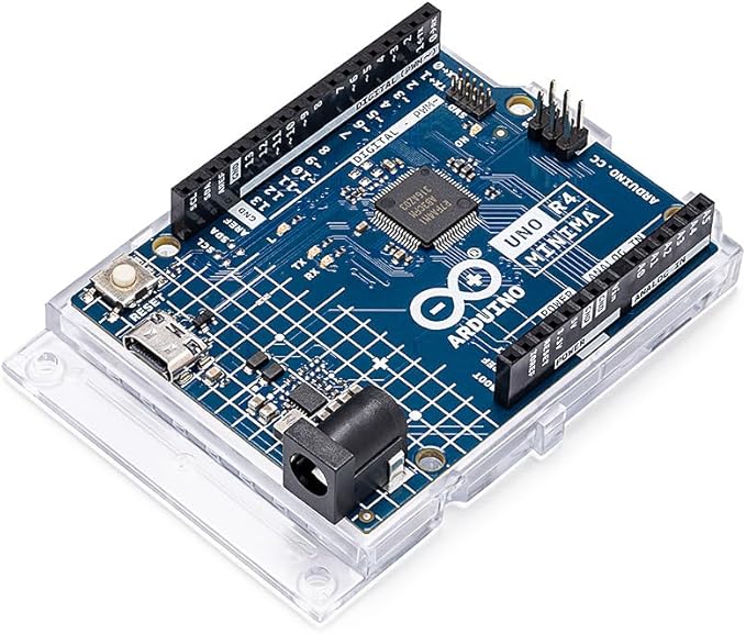
Arduino UNO R4 Minima

Arduino UNO R4 Minima starter kit
RGB LED Structure and How It Works
Three LED Chips in One Package
An RGB full-color LED contains three LED chips inside a single transparent package:
- R (Red): ~620–630 nm wavelength
- G (Green): ~515–530 nm wavelength
- B (Blue): ~460–470 nm wavelength
These are the three primary colors of light — the basic components that human cone cells detect.
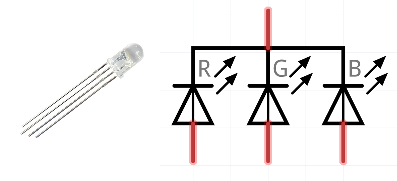
Internal structure of an RGB full-color LED (common-cathode type)
Common-Cathode vs. Common-Anode
RGB LEDs come in two configurations:
| Type | Common Pin | Each color pin | Arduino control |
|---|---|---|---|
| Common-Cathode | GND (−) | HIGH = ON | digitalWrite(R, HIGH) |
| Common-Anode | VCC (+) | LOW = ON | digitalWrite(R, LOW) |
This guide uses common-cathode. Each color’s anode (+) connects to an Arduino digital pin; the common cathode (−) connects to GND.
Additive Color Mixing
Combining RGB channels produces these colors:
| R | G | B | Result |
|---|---|---|---|
| ● | ○ | ○ | Red |
| ○ | ● | ○ | Green |
| ○ | ○ | ● | Blue |
| ● | ● | ○ | Yellow |
| ● | ○ | ● | Magenta |
| ○ | ● | ● | Cyan |
| ● | ● | ● | White |
| ○ | ○ | ○ | Off |
(● = ON, ○ = OFF)
That’s 2³ = 8 combinations. But if you control each channel’s brightness, you get 256 × 256 × 256 = 16,777,216 colors — which is what PWM enables.
Parts List
| Part | Spec | Qty | Notes |
|---|---|---|---|
| Arduino UNO | R3 or R4 Minima | 1 | Must have PWM pins |
| RGB full-color LED | Common-cathode, 4 pins | 1 | 5mm diffused recommended |
| Resistor | 220Ω (1/4W) | 3 | One per color channel |
| Breadboard | Standard size | 1 | — |
| Jumper wires | Male-to-male | 4 | — |
STEP 1: 8-Color Control with Digital Output
Circuit Design
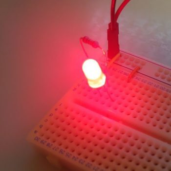
Start simple — just ON/OFF per channel.

Basic RGB LED circuit (common-cathode)
Key circuit points:
-
Current-limiting resistors are mandatory
Connect a 220Ω resistor in series with each color channel. Arduino UNO outputs 5V; RGB LED forward voltages are ~2.0V (red) and ~3.2V (green/blue). Without resistors, excess current destroys the LED.Current calculation: Red: I = (5V − 2.0V) / 220Ω ≈ 13.6 mA Green/Blue: I = (5V − 3.2V) / 220Ω ≈ 8.2 mA Both well under the 20 mA LED rating ✓ -
Use PWM-capable pins from the start
For STEP 2, use PWM pins (Arduino UNO: 3, 5, 6, 9, 10, 11) so you don’t need to rewire later:- Pin 9 → Red (R)
- Pin 10 → Blue (B)
- Pin 11 → Green (G)
-
Common cathode goes to GND
The longest pin on the RGB LED (common cathode) connects to Arduino GND.
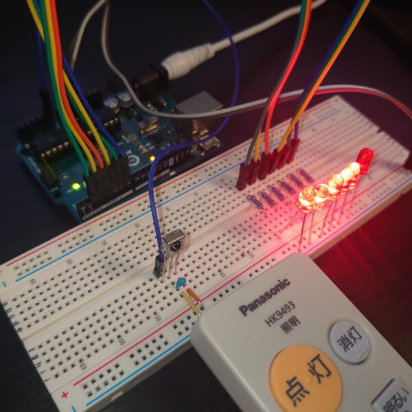
Sample Code: 8-Color Cycle
#define R 9    // Red
#define G 11   // Green
#define B 10   // Blue

void setup() {
   pinMode(R, OUTPUT);
   pinMode(G, OUTPUT);
   pinMode(B, OUTPUT);
}

void loop() {
   // 1. Red
   digitalWrite(R, HIGH); delay(500); digitalWrite(R, LOW);
   // 2. Green
   digitalWrite(G, HIGH); delay(500); digitalWrite(G, LOW);
   // 3. Blue
   digitalWrite(B, HIGH); delay(500); digitalWrite(B, LOW);
   // 4. Yellow (Red + Green)
   digitalWrite(R, HIGH); digitalWrite(G, HIGH);
   delay(500);
   digitalWrite(R, LOW); digitalWrite(G, LOW);
   // 5. Cyan (Green + Blue)
   digitalWrite(G, HIGH); digitalWrite(B, HIGH);
   delay(500);
   digitalWrite(G, LOW); digitalWrite(B, LOW);
   // 6. Magenta (Red + Blue)
   digitalWrite(R, HIGH); digitalWrite(B, HIGH);
   delay(500);
   digitalWrite(R, LOW); digitalWrite(B, LOW);
   // 7. White (all on)
   digitalWrite(R, HIGH); digitalWrite(G, HIGH); digitalWrite(B, HIGH);
   delay(500);
   // 8. Off
   digitalWrite(R, LOW); digitalWrite(G, LOW); digitalWrite(B, LOW);
   delay(500);
}
Demo Video
Troubleshooting
| Symptom | Cause | Fix |
|---|---|---|
| LED doesn’t light at all | Wiring error or reverse polarity | Verify cathode (longest pin) is at GND |
| One color doesn’t work | Broken wire or missing resistor | Re-check that channel’s connections |
| LED burns out immediately | Missing current-limiting resistor | Always use 220Ω on each channel |
| Colors look mixed | Diffused LED characteristic | Normal — this is additive mixing as expected |
STEP 2: 16.7 Million Colors with PWM
How PWM Works
Digital pins only output HIGH (5V) or LOW (0V). But by switching rapidly between the two states and varying the ON-time ratio (duty cycle), you can produce an effective analog voltage. That’s PWM (Pulse Width Modulation).
Duty cycle   0% (always LOW)  → effective voltage 0V   (off)
Duty cycle  50% (half and half) → effective voltage 2.5V (mid brightness)
Duty cycle 100% (always HIGH) → effective voltage 5V   (full brightness)
Arduino UNO’s PWM has 8-bit (256-step) resolution, giving each channel a 0–255 range:
256 (R) × 256 (G) × 256 (B) = 16,777,216 colors
Using analogWrite()
analogWrite(pin, value); // value: 0 (off) to 255 (full brightness)
Important: On Arduino UNO, PWM is only available on pins 3, 5, 6, 9, 10, 11.
Three-Phase Sine Wave for Smooth Color Gradients
Drive each channel’s brightness along a sine curve, with each channel’s phase offset by 120 degrees (85 steps). The result is a smooth rainbow cycle.
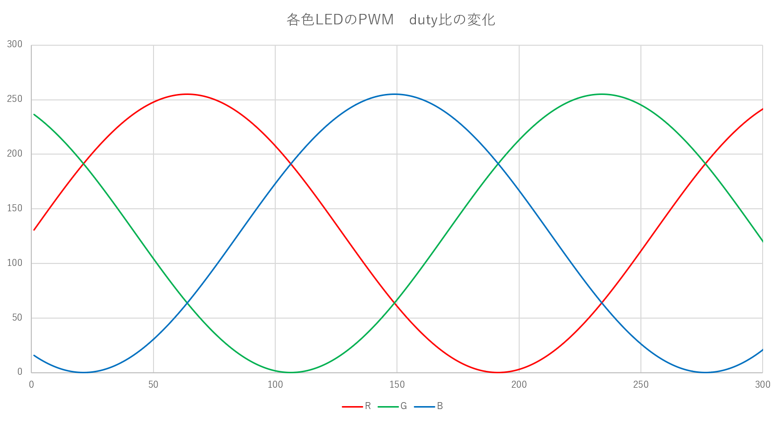
Three-phase sine wave phase control (each channel offset by 85 steps)
Phase offsets:
- Red (R): 0° (reference)
- Green (G): 120° (offset by 85 steps)
- Blue (B): 240° (offset by 170 steps)
When red is at peak brightness, green and blue are at intermediate or low brightness. As time passes, the brightness balance continuously shifts, producing a cycling gradient: red → orange → yellow → green → cyan → blue → purple → red…
Sample Code: 16.7M Color Gradient
#define R 9    // Red
#define G 11   // Green
#define B 10   // Blue

void setup() {
   pinMode(R, OUTPUT);
   pinMode(G, OUTPUT);
   pinMode(B, OUTPUT);
}

void loop() {
   uint8_t r, g, b;
   uint8_t i;

   for (i = 0;; i++) {  // infinite loop; i overflows naturally as uint8_t
      // Scale sin() output from [-1, +1] to [0, 255]
      r = (sin(2 * 3.14 / 255 * i) + 1) * (255 / 2);
      g = (sin(2 * 3.14 / 255 * (i + 85)) + 1) * (255 / 2);   // 120° phase offset
      b = (sin(2 * 3.14 / 255 * (i + 170)) + 1) * (255 / 2);  // 240° phase offset

      analogWrite(R, r);
      analogWrite(G, g);
      analogWrite(B, b);

      delay(20);  // update every 20ms → one full cycle ≈ 5 seconds
   }
}
Code breakdown:
-
Smooth brightness with sine function
2 * 3.14= 2π (one full cycle)/ 255completes the cycle in 255 stepsicycles through 0–255 via uint8_t overflow
-
Scaling −1…+1 to 0…255
+ 1shifts range to 0…2* (255 / 2)expands to 0…255
-
Why 85 steps of phase offset
360° / 3 channels = 120°
255 steps × (120 / 360) ≈ 85 steps
Demo Video
What to check:
- ✅ Colors transition smoothly, not abruptly
- ✅ Cycling: red → orange → yellow → green → blue → purple
- ✅ One full cycle in approximately 5 seconds (255 steps × 20 ms)
- ✅ No visible flicker (PWM at ~490/980 Hz is invisible to the human eye)
Customization Ideas
Adjust Gradient Speed
delay(5);   // fast (~1.3 sec/cycle) — disco effect
delay(20);  // default (~5 sec/cycle) — calm ambiance
delay(100); // slow (~25 sec/cycle) — meditative
Sensor-Driven Color
Map an analog sensor value (temperature, light) to RGB brightness:
int sensorValue = analogRead(A0);  // 0–1023
int brightness = map(sensorValue, 0, 1023, 0, 255);
analogWrite(R, brightness);
analogWrite(G, 255 - brightness);  // inverse
analogWrite(B, 128);               // fixed
Multiple RGB LEDs
- Shift register (74HC595): control many LEDs with few pins
- WS2812B (NeoPixel): individually control hundreds of LEDs over a single wire
Summary
What You Learned
✅ Additive color mixing — RGB combinations produce 8+ colors
✅ 8-color digital control — digitalWrite() basics, common-cathode wiring
✅ PWM with analogWrite() — 256-step brightness → 16.7M colors
✅ Three-phase sine wave control — mathematical approach to beautiful gradients
Where PWM Goes Next
PWM techniques apply far beyond LED control:
- DC motor speed control — vary rotation speed
- Servo motor control — angle positioning (internally uses PWM)
- Speaker driving —
tone()for melody playback - Dimmer circuits — stepless brightness control for white LEDs
Related Articles
FAQ
Q1. I have a common-anode RGB LED. What changes?
Connect the anode (longest pin) to 5V/VCC, and connect each color’s cathode to Arduino pins. Logic is inverted: digitalWrite(R, LOW) turns it on; analogWrite(R, 255 - brightness) for PWM control.
Q2. Can I change the PWM frequency?
Yes, but it requires direct timer register manipulation. For most uses, the defaults (pins 5/6 ≈ 980 Hz; pins 3/9/10/11 ≈ 490 Hz) are fine.
Q3. How do I synchronize multiple RGB LEDs to the same color?
Connect the corresponding color pins in parallel. Keep total current under Arduino’s 40 mA per-pin limit; use a transistor driver if needed.
Q4. The LED flickers when running on batteries.
Insufficient power supply. Full-brightness RGB LEDs draw up to 60 mA (20 mA × 3). Use 4× AA batteries (6V) with a regulator, or a 5V USB power bank.
Q5. I want to control many LEDs individually.
Use addressable LEDs like WS2812B (NeoPixel) or APA102 — hundreds of individually controllable full-color LEDs over a single data wire.