Introduction: Control Electronics with Any IR Remote
The infrared remote sitting next to your TV can do far more than change channels. By receiving its signals with a microcontroller, you unlock a wide range of IoT applications:
- Smart home logging — automatically record appliance states
- Unified remote — control multiple devices from one remote
- Automation triggers — IR signals kick off automated sequences
- Universal remote — capture and re-transmit any IR signal
This project builds a system using Arduino UNO, an IR receiver module (OSRB38C9AA), and the IRremote library to receive signals from a household remote and control 6 LEDs accordingly.
We’ll cover the underlying IR communication principles, how to decode signals, and how to build a practical control program — both hardware and software.
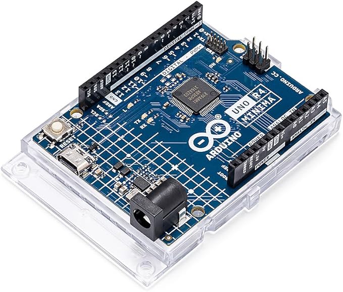
Arduino UNO R4 Minima
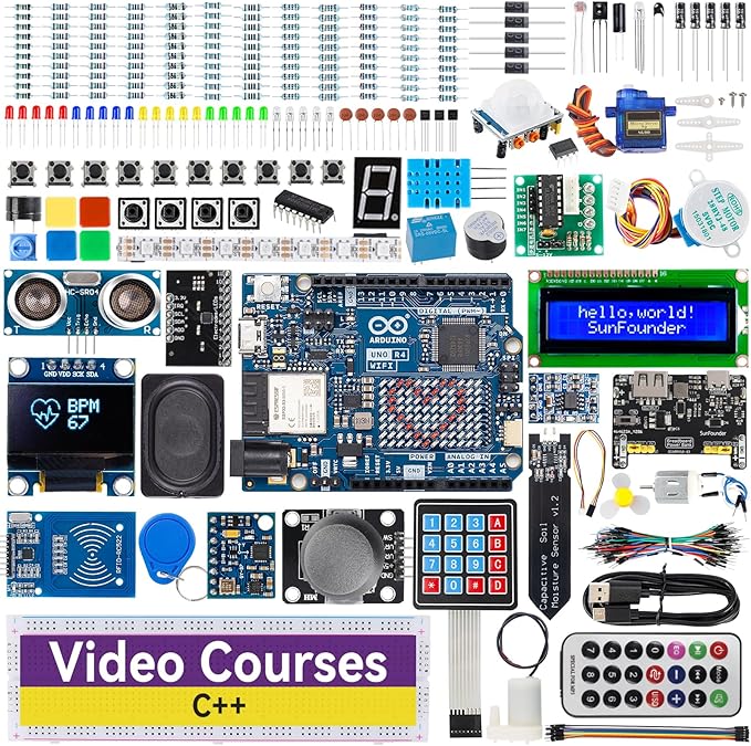
Arduino UNO R4 Minima starter kit
How Infrared Remote Controls Work
What Is Infrared?
Infrared (IR) is electromagnetic radiation with wavelengths longer than visible light. Humans can’t see it, but we can feel it as heat. Its properties make it ideal for remote controls.
Wavelength (nm)  Type              Use
200–380          Ultraviolet       Sterilization
380–700          Visible light     Displays, lighting
700–1400         Near-infrared     Remote controls ← this project
1400–3000        Mid-infrared      Heating, sensors
Why IR is used for remote controls:
| Property | Detail | Advantage |
|---|---|---|
| Wavelength | ~850–950 nm (near-IR) | Easy to produce with LEDs |
| Directionality | Relatively line-of-sight | Targets specific devices only |
| Wall penetration | Does not penetrate walls | No interference with adjacent rooms |
| Cost | Extremely cheap components | Mass production friendly |
| Power consumption | Very low | Battery-powered operation for years |
The 38 kHz Modulation Trick
IR remotes use 38 kHz carrier modulation to distinguish the remote’s signal from ambient IR (sunlight, room lighting). The receiver’s built-in bandpass filter passes only the 38 kHz band — everything else is blocked as noise.
Common IR Protocols
| Protocol | Main devices | Carrier | Bit length |
|---|---|---|---|
| NEC | Generic remotes, lighting | 38 kHz | 32 bits |
| SONY | Sony TVs, AV equipment | 40 kHz | 12/15/20 bits |
| RC-5/RC-6 | Philips products | 36 kHz | 13/32 bits |
| Samsung | Samsung products | 38 kHz | 32 bits |
The IRremote library automatically detects and decodes all major protocols.
How the IR Receiver Module Works
The OSRB38C9AA (and equivalents like TSOP38238) integrates four functions into one package:
- Photodiode: converts IR light to electrical signal
- AGC (Automatic Gain Control): adjusts sensitivity automatically
- Bandpass filter: passes only the 38 kHz band
- Demodulator: removes the carrier, outputs a clean digital signal
Arduino simply reads HIGH/LOW on a digital pin — no complex signal processing needed.
Parts List
Signal Reception
| Part | Spec | Qty | Notes |
|---|---|---|---|
| Arduino UNO | R3 / R4 Minima | 1 | R4 recommended |
| IR receiver module | OSRB38C9AA (38 kHz) | 1 | TSOP38238 also works |
| IR remote control | TV / lighting / AC unit | 1 | NEC or SONY protocol recommended |
| Breadboard | Standard size | 1 | 400-hole type |
| Jumper wires | Male-to-male | 3+ | — |
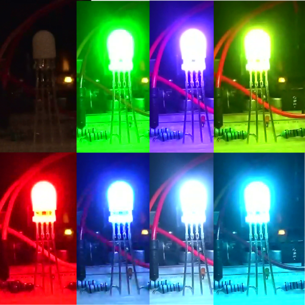
LED Control
| Part | Spec | Qty |
|---|---|---|
| Red LED | Vf = 1.8–2.2V | 6 |
| Resistor | 220Ω (1/4W) | 6 |
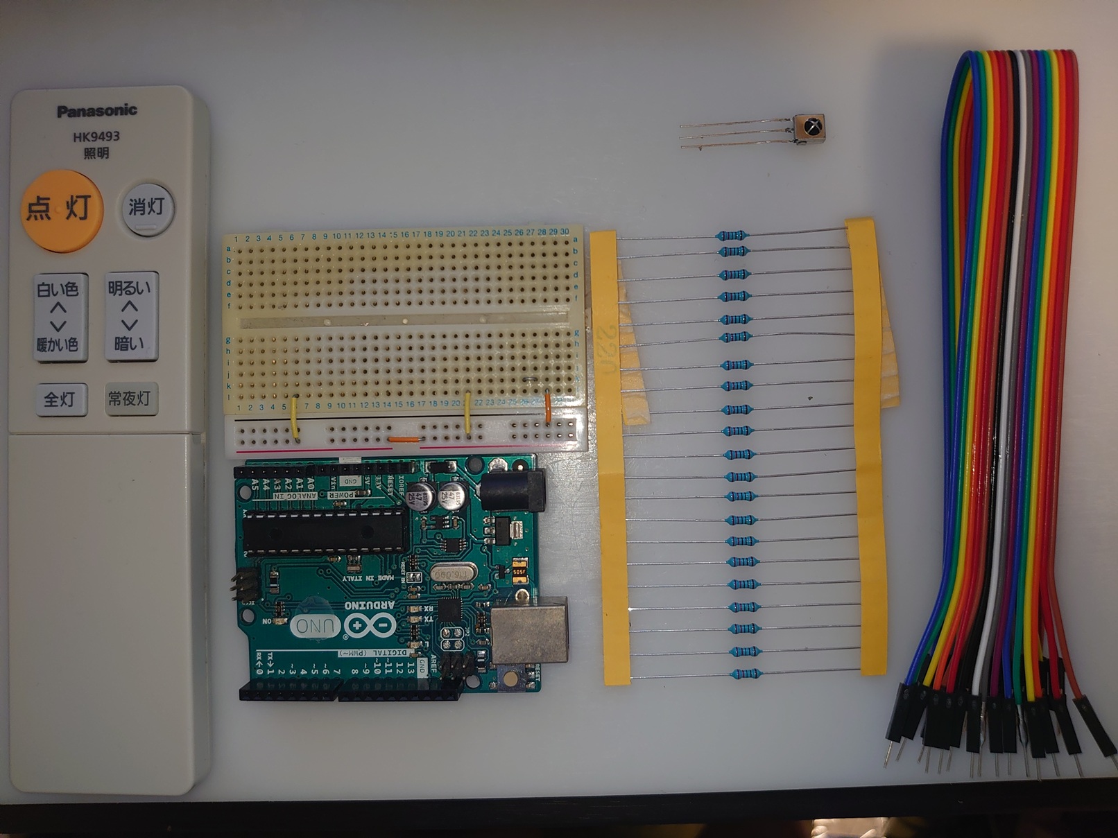
All parts assembled
No remote at home? Electronics-specific IR remote modules (pre-programmed with known codes) are available cheaply and work great for projects like this.
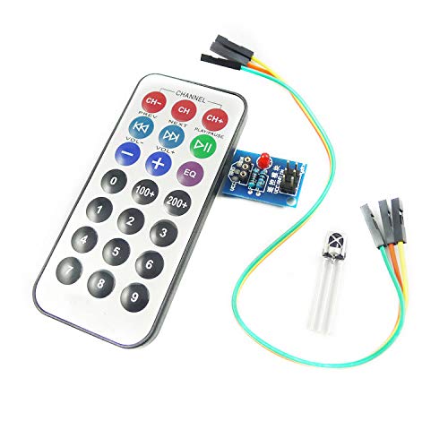
Electronics project IR remote
Step 1: Receive and Decode IR Signals
Install the IRremote Library
- Open Arduino IDE
- Sketch → Include Library → Manage Libraries…
- Search for IRremote
- Install shirriff/IRremote (or a compatible version)
Wiring the IR Receiver
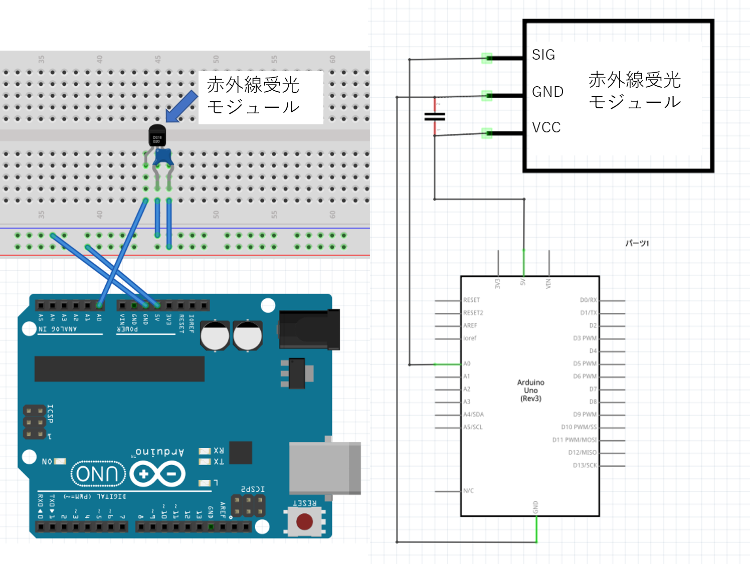
IR receiver module wiring diagram
OSRB38C9AA pin connections:
| Pin | Signal | Connect to |
|---|---|---|
| 1 | OUT | Arduino A0 |
| 2 | GND | Arduino GND |
| 3 | VCC | Arduino 5V |
Important:
- Orient the receiver so its sensing face points outward toward the remote
- For long cable runs, add a 0.1 µF bypass capacitor between VCC and GND
- Any digital (D2–D13) or analog (A0–A5) pin works for input
Signal Capture Program
This program receives IR signals and prints them as hexadecimal codes on the Serial Monitor.
#include <IRremote.h>

int RECV_PIN = A0;
IRrecv irrecv(RECV_PIN);
decode_results results;

void setup() {
  Serial.begin(9600);
  irrecv.enableIRIn();  // Start IR receiver
  Serial.println("IR Receiver Ready");
}

void loop() {
  if (irrecv.decode(&results)) {
    Serial.print("Received: 0x");
    Serial.println(results.value, HEX);

    Serial.print("Protocol: ");
    Serial.println(results.decode_type);

    irrecv.resume();  // Ready for next signal
  }
  delay(100);
}
| Function | Purpose |
|---|---|
irrecv.enableIRIn() |
Activate receiver (call once in setup) |
irrecv.decode(&results) |
Returns true when signal received; fills results struct |
results.value |
Received signal value (unsigned long) |
results.decode_type |
Protocol type: NEC=1, SONY=2, RC5=3, etc. |
irrecv.resume() |
Clear buffer, prepare for next signal |
How to Capture Your Remote’s Codes
- Upload the program to Arduino
- Open Serial Monitor (Tools → Serial Monitor, 9600 baud)
- Point your remote at the receiver and press a button
- Read the hex code from Serial Monitor
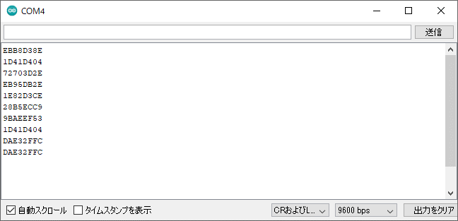
Serial Monitor showing received IR signals
Tips:
- Press each button multiple times and verify the code is consistent
- If codes vary, adjust distance/angle between remote and receiver
- Long presses may show
FFFFFFFF(repeat code) — that’s normal
Example Codes Captured (Room Light Remote, NEC Protocol)
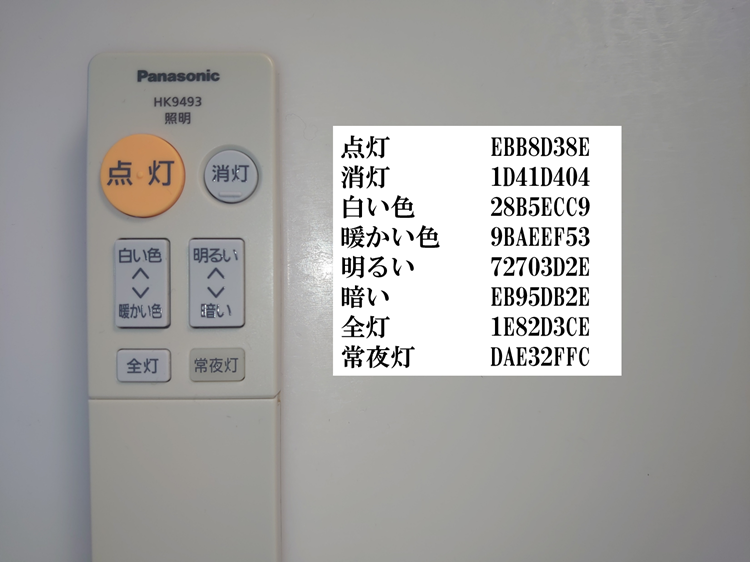
IR signal code table for room light remote
| Button | Hex Code | Planned Function |
|---|---|---|
| ON | 0xEBB8D38E | 3 LEDs on (medium) |
| FULL BRIGHT | 0x1E82D3CE | All 6 LEDs on |
| OFF | 0x1D41D404 | All LEDs off |
| BRIGHTER | 0x72703D2E | Add one LED at a time |
| DIMMER | 0xEB95DB2E | Remove one LED at a time |
These codes are unique to your remote — you must capture your own. Any NEC remote will have completely different values.
Step 2: LED Control System
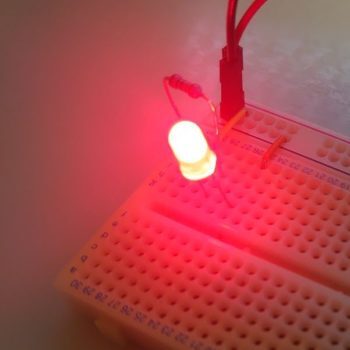
LED Circuit Design
Wire 6 LEDs on digital pins D2–D7, each with a 220Ω current-limiting resistor.
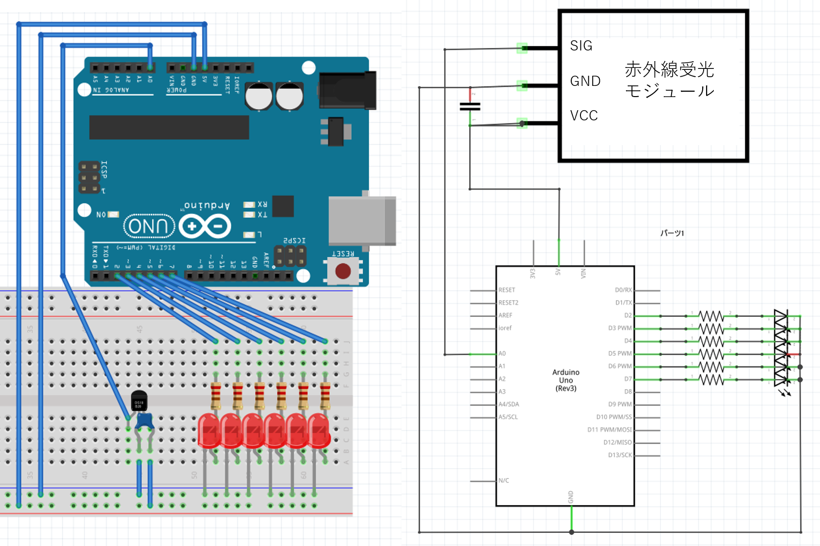
Complete IR remote LED control circuit
Circuit design points:
- LED pins: D2–D7 (6 individual LEDs)
- Current-limiting resistors: 220Ω each — (5V − 2V) / 0.015A ≈ 200Ω; 220Ω gives safe margin
- IR receiver: stays on A0
- GND: share the breadboard power rail
Button-to-Function Mapping
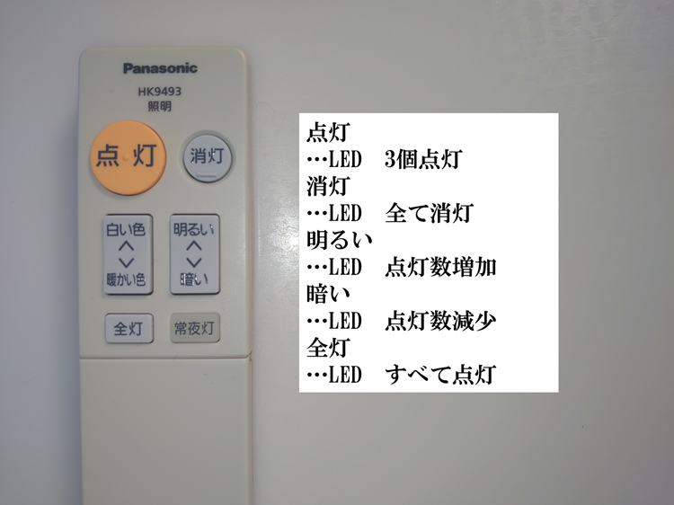
Remote button function mapping
| Button | Code | Action | LED State |
|---|---|---|---|
| ON | 0xEBB8D38E | 3 LEDs on (medium) | D2, D3, D4 = ON |
| FULL BRIGHT | 0x1E82D3CE | All 6 LEDs on | D2–D7 = ON |
| OFF | 0x1D41D404 | All LEDs off | D2–D7 = OFF |
| BRIGHTER | 0x72703D2E | Add one LED | Step up |
| DIMMER | 0xEB95DB2E | Remove one LED | Step down |
Control logic: variable j tracks brightness level (1–7); BRIGHTER/DIMMER increment/decrement it.
Complete LED Control Program
#include <IRremote.h>

int RECV_PIN = A0;
int i, j;  // i: loop counter; j: current brightness level (1-7)

IRrecv irrecv(RECV_PIN);
decode_results results;

void setup() {
  Serial.begin(9600);
  irrecv.enableIRIn();

  // Set D2-D7 as outputs; start all off
  for (i = 2; i <= 7; i++) {
    pinMode(i, OUTPUT);
    digitalWrite(i, LOW);
  }

  j = 1;  // Initial brightness level: all off
  Serial.println("LED Control System Ready");
}

void loop() {
  if (irrecv.decode(&results)) {
    Serial.print("Received: 0x");
    Serial.println(results.value, HEX);

    irrecv.resume();

    switch (results.value) {

      case 0xEBB8D38E:  // ON button
        for (i = 2; i < 5; i++) digitalWrite(i, HIGH);  // D2, D3, D4 on
        for (i = 5; i < 8; i++) digitalWrite(i, LOW);   // D5, D6, D7 off
        j = 4;
        Serial.println("Mode: Normal (LEDs 0-2 ON)");
        break;

      case 0x1E82D3CE:  // FULL BRIGHT button
        for (i = 2; i < 8; i++) digitalWrite(i, HIGH);  // All on
        j = 7;
        Serial.println("Mode: Full Brightness");
        break;

      case 0x1D41D404:  // OFF button
        for (i = 2; i < 8; i++) digitalWrite(i, LOW);   // All off
        j = 1;
        Serial.println("Mode: OFF");
        break;

      case 0x72703D2E:  // BRIGHTER button
        j++;
        if (j > 7) j = 7;  // Upper limit
        digitalWrite(j, HIGH);
        Serial.print("Brightness UP: Level "); Serial.println(j - 1);
        break;

      case 0xEB95DB2E:  // DIMMER button
        digitalWrite(j, LOW);
        j--;
        if (j < 1) j = 1;  // Lower limit
        Serial.print("Brightness DOWN: Level "); Serial.println(j - 1);
        break;

      default:
        Serial.println("Unknown button");
        break;
    }

    delay(300);  // Debounce
  }
}
Key implementation points:
-
State variable
j
Tracks current brightness (1 = all off, 7 = all on). Maps directly to pin numbers D2–D7 (pin = j + 1). -
Step-by-step dimming
BRIGHTER:digitalWrite(j, HIGH); j++
DIMMER:digitalWrite(j, LOW); j--
Bounds checking prevents out-of-range pin access. -
Debounce
delay(300)prevents multiple triggers from one press. For non-blocking behavior, usemillis()instead. -
Debug output
Serial prints confirm which button was received. Remove Serial code in production to reduce overhead.
Demo Video
What you should see:
- LEDs respond instantly when a button is pressed
- BRIGHTER/DIMMER buttons step the LEDs up or down one at a time
- Reception range: ~3–5 meters (varies by environment)
- Works at angles up to ~45° from the receiver’s face
Applications and Extensions
Learning Remote
- Save received signals to EEPROM (non-volatile memory)
- Add an IR LED transmitter circuit
- Replay stored signals to control the original appliance
Smart Home Integration
Connect an ESP32/ESP8266 to add Wi-Fi and send IR codes to an MQTT broker or home automation platform like Home Assistant.
Multi-Remote Unifier
Capture signals from multiple remotes and build a single unified controller for all devices in a room.
Summary
| Learned | Detail |
|---|---|
| IR communication principles | 38 kHz modulation, NEC/SONY protocols |
| IRremote library usage | enableIRIn(), decode(), resume() |
| Signal capture | Read hex codes via Serial Monitor |
| LED control logic | switch() on signal values, state variable dimming |
Next Steps
- Beginner: Add more buttons — temperature sensor color mapping
- Intermediate: Store codes in EEPROM; build a learning remote
- Advanced: ESP32 + MQTT + Home Assistant integration